High-efficiency power converter system

a power converter and high-efficiency technology, applied in the direction of dc-dc conversion, conversion with intermediate conversion to dc, and efficient power electronics conversion, etc., can solve the problems of substantial losses when such switches are turned on and off, and loss may also occur in the power converter

Active Publication Date: 2008-01-03
SEMICON COMPONENTS IND LLC
View PDF5 Cites 96 Cited by
  • Summary
  • Abstract
  • Description
  • Claims
  • Application Information

AI Technical Summary

Benefits of technology

[0008]Important technical advantages of the present invention are readily apparent to one skilled in the art from the following figures, descriptions, and claims.

Problems solved by technology

Substantial losses may occur when such switches are turned on and off under certain conditions.
Losses may also occur in a power converter due to the flow of current through various circuit components (e.g., diodes) which have an associated forward conduction power loss.

Method used


Image

  • High-efficiency power converter system
  • High-efficiency power converter system
  • High-efficiency power converter system

Examples


Embodiment Construction

[0022]Embodiments of the present invention and their advantages are best understood by referring to FIGS. 1 through 14 of the drawings. Like numerals are used for like and corresponding parts of the various drawings.

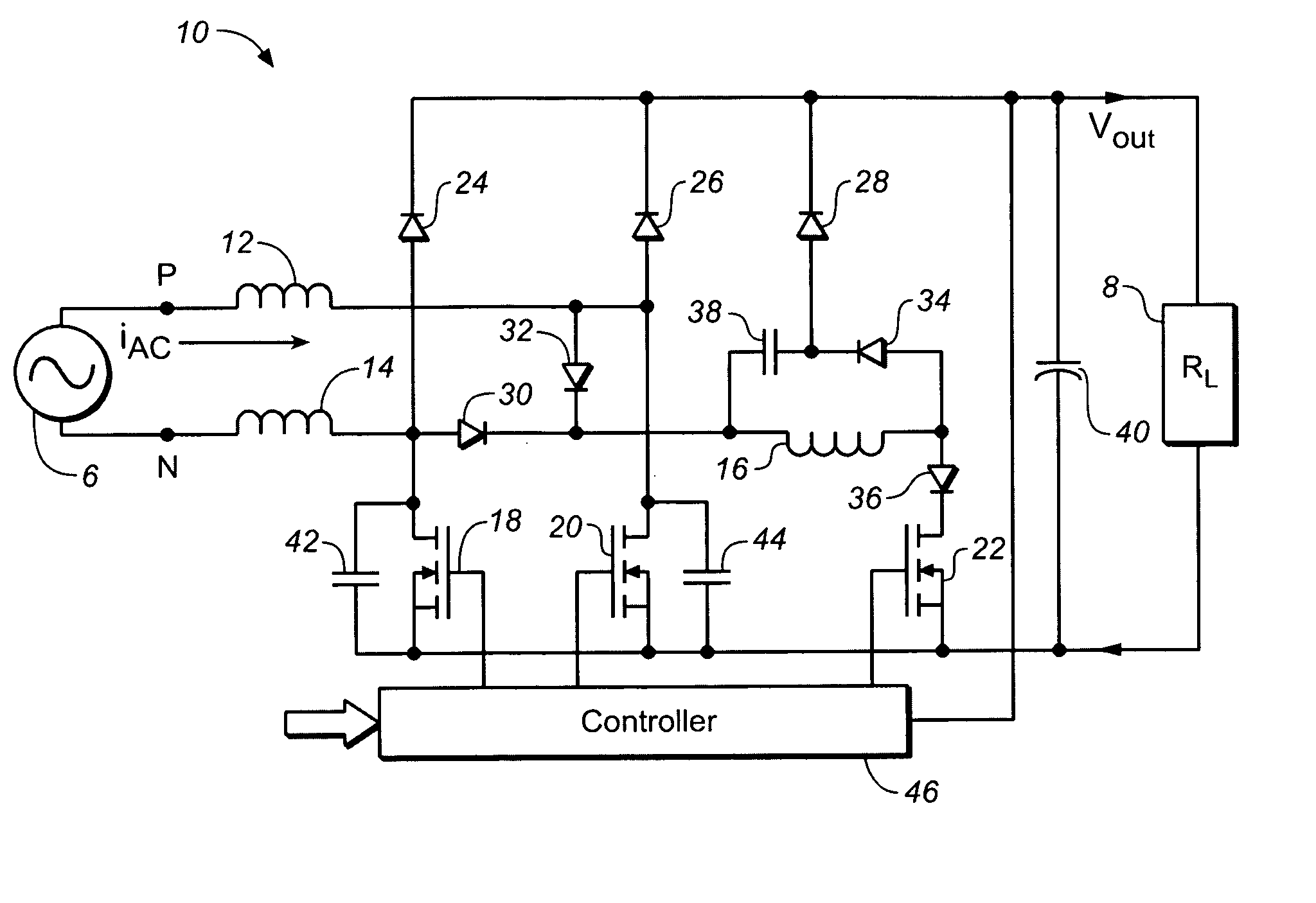
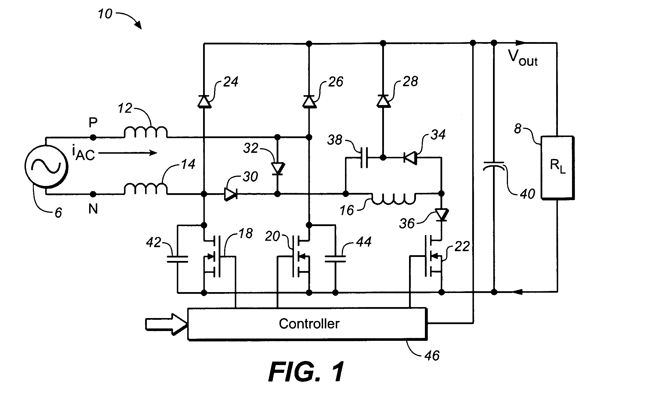
[0023]In one embodiment, an AC-to-DC power converter system is provided which integrates input side rectification and soft-switched power factor correction (PFC). For soft-switched PFC, various switches in the power converter system are turned on and off under zero voltage switching (ZVS) and / or zero current switching (ZCS) conditions. The converter system may be capable of true synchronous rectification. The power converter system may include circuitry for input side rectification, boost, and soft-switched PFC.

[0024]Furthermore, in some embodiments, the present invention increases converter efficiency by reducing conduction losses as well as switching losses. In some embodiments, this reduces heat sink size as well as increases power density.

[0025]FIG. 1 is a schematic ...


PUM


Abstract

In one embodiment, a power converter system includes a first input terminal and a second input terminal operable to connect to an alternating current (AC) power source, and an output terminal at which an output voltage can be provided to a load. A first inductor and a first diode are connected in series between the first input terminal and the output terminal. A second inductor and a second diode are connected in series between the second input terminal and the output terminal. A first switch is connected to the first inductor and the first diode, and a second switch is connected to the second inductor and the second diode. The first switch and the second switch alternately function as a boost switch and a synchronous rectifier for charging and discharging the first and second inductors during operation of the power converter system. An auxiliary network is operable to provide for zero voltage switching (ZVS) and zero current switching (ZCS) conditions for both the first and second switches during operation of the power converter system.

Description

BACKGROUND[0001]1. Field of Invention[0002]The present invention relates to power conversion, and more particularly, to a high-efficiency power converter system.[0003]2. Description of Related Art[0004]Power converters are essential for many modern electronic devices. Among other capabilities, power converters can adjust voltage level downward (buck converter) or adjust voltage level upward (boost converter). Power converters may also convert from alternating current (AC) power to direct current (DC) power, or vice versa. Power converters are typically implemented using one or more switching devices, such as transistors, which are turned on and off to deliver power to the output of the converter. Substantial losses may occur when such switches are turned on and off under certain conditions. Losses may also occur in a power converter due to the flow of current through various circuit components (e.g., diodes) which have an associated forward conduction power loss. It is desirable to ...

Claims


Application Information

Patent Timeline
Patent Type & Authority Applications(United States)
IPC IPC(8): H02M7/217
CPCH02M1/34Y02B70/126H02M1/4225Y02B70/10H02M1/0085H02M1/42H02M3/155
Inventor SHEKHAWAT, SAMPATRANDALL, RONALD H.CHO, DONGHYE
Owner SEMICON COMPONENTS IND LLC
Why Eureka
Try Eureka