

Angled hose connection for dental handpiece
- Summary
- Abstract
- Description
- Claims
- Application Information
AI Technical Summary
Benefits of technology
Problems solved by technology
Method used
Image

Examples
Embodiment Construction
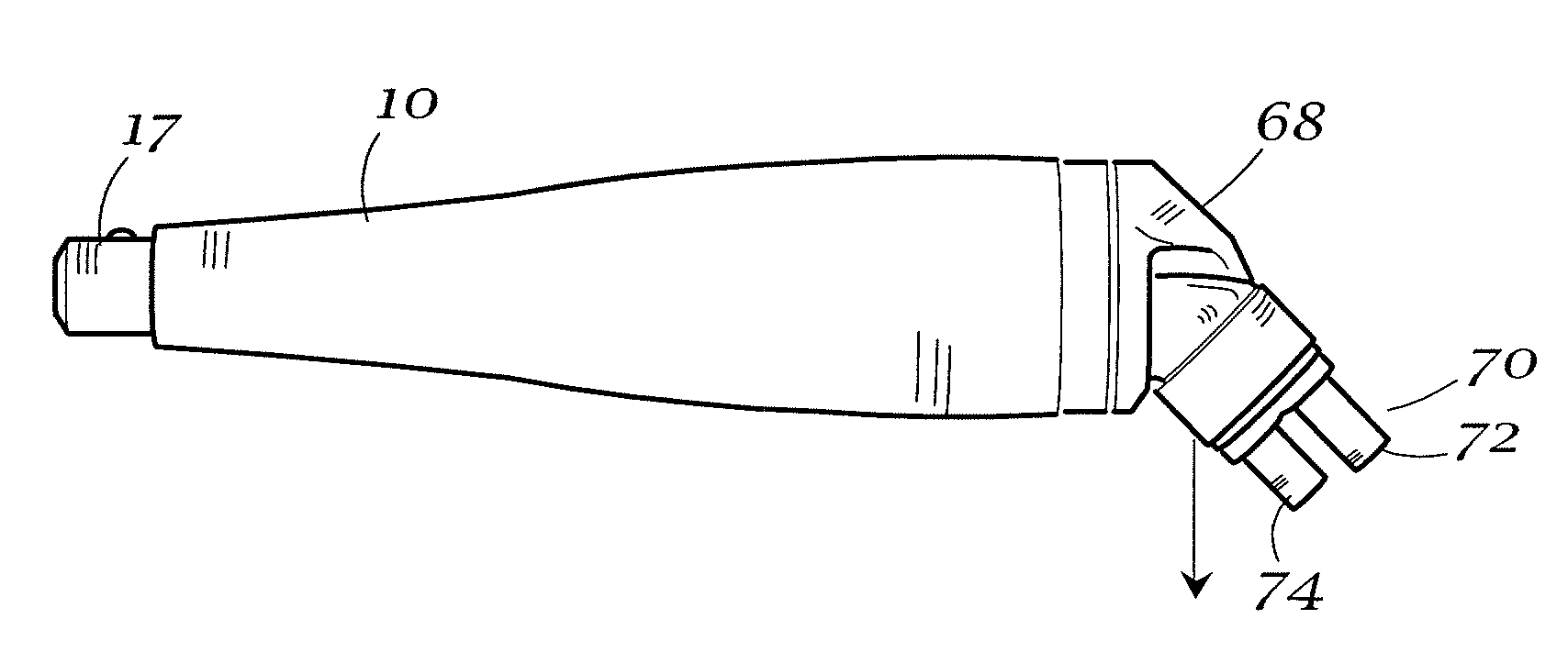
[0022] The handpiece assembly of the present invention modifies the proximal end of a dental handpiece so as to reduce the strain on the dental professional's hand. The proximal end of this handpiece is provided with a preselected angle. A flexible supply hose is attached to the proximal end so that bending of the supply hose in the region of the connection is minimized. In accordance with some current designs, the proximal end includes a swivel attachment to allow free rotation between the flexible supply and the coupler, usually at their interface. The preselected angle results in a reduction of the load resisting gravity in the attachment region. In addition to reducing the stress, the remaining load is applied closer to the handpiece resulting in a further reduction of moment, the moment being a product of the load and distance. The effect of the present invention is to reduce the applied load and to reduce the moment by moving the position of the resulting load closer to the gr...
PUM
 Abstract
Description
Claims
Application Information