Floor or wall covering

a technology for floor or wall coverings and tiles, applied in the direction of flooring, sustainable buildings, decorative arts, etc., can solve the problems of large installation and installation preparation time, large installation preparation time, and difficult installation process, so as to prolong the life and performance of the floor covering

Inactive Publication Date: 2008-01-10
DOMBOWSKY MICHAEL
View PDF16 Cites 20 Cited by
  • Summary
  • Abstract
  • Description
  • Claims
  • Application Information

AI Technical Summary

Benefits of technology

[0035]The panels can be installed over existing flooring including cracked concrete, old ceramic or vinyl tile or new wood or concrete substrates by applying urethane foam from a gun dispenser into which the panel is laid and additional panels are laid next to and interlocked with the adjacent panel to form one entire connected surface which essentially floats over the existing floor providing a resilient floor that will flex but not crack, thereby greatly extending the life and performance of the floor covering.
[0036]Thus another features is to provide a method for creating a resilient and durable panel flooring that can be created in a plant in a more completed form and in larger sheets thereby allowing several tiles to be arrayed on the panel, which may include accent tile or mosaics, all applied to the surface of the sheet metal. After the polymer cementitious coating or other cures, color and clear coat is added and again cured. Next, all grout lines on the interior of the larger sheet are grouted with a latex grout. All of these processes are done on a tabletop for easy access instead of on the knees for traditional tile setting.
[0037]A second object of the present invention is to provide a method for installing the tile over a variety of substrates without the need of traditional tile setters. This is accomplished by laying the flexible 14 to 16 gauge sheet metal tiles onto the floor, which is glued to the floor with polyurethane foam, dispensed from a gun applicator in rows 6 inches on center. This allows the new metal-stone to be resilient. Each tile is locked into the next tile by tapping the opposing angled mortise shapes together, which is stamped out of the perimeter of the tile in the plant. This connecting of each tile creates an entirely joined floor in all directions and in turn, allows the metal-stone floor tile to float over any stable substrate. After all tile are laid over the existing floor, the locked joints of the tile are sealed with a liquid sealer which prevents water penetration and welds each metal sheet together with liquid glue. Next, the joints are grouted to match the tile in the center of each larger tile that was grouted in the plant.

Problems solved by technology

However, ceramic and porcelain and stone tile flooring has changed very little and while the marketplace desires hard surface floor coverings that are attractive and durable, ceramic and porcelain are by nature heavy, hard and brittle, time consuming to install and require extensive surface preparation for installation.
In addition when it comes to changing the floor covering the process of removing ceramic and porcelain and stone is messy and time consuming.

Method used


Image

  • Floor or wall covering
  • Floor or wall covering
  • Floor or wall covering

Examples


Embodiment Construction

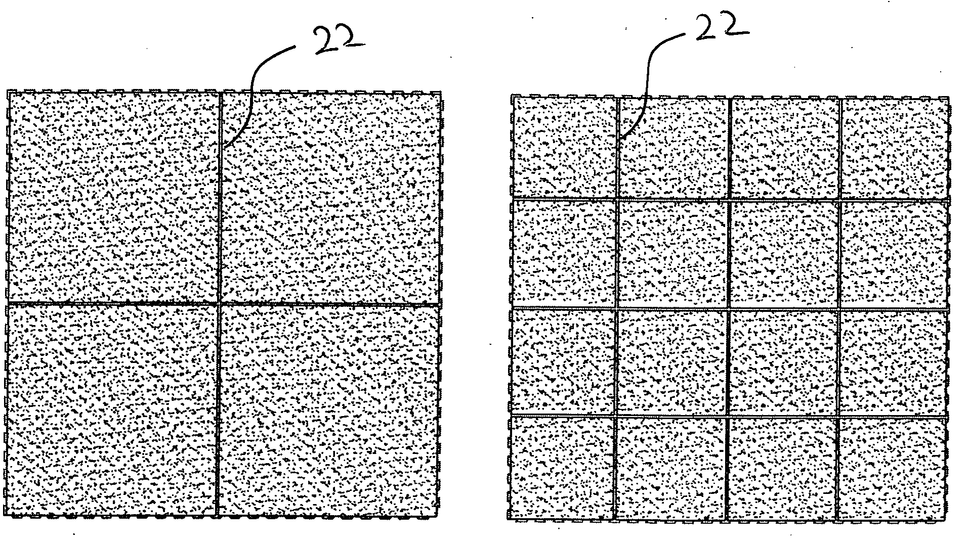
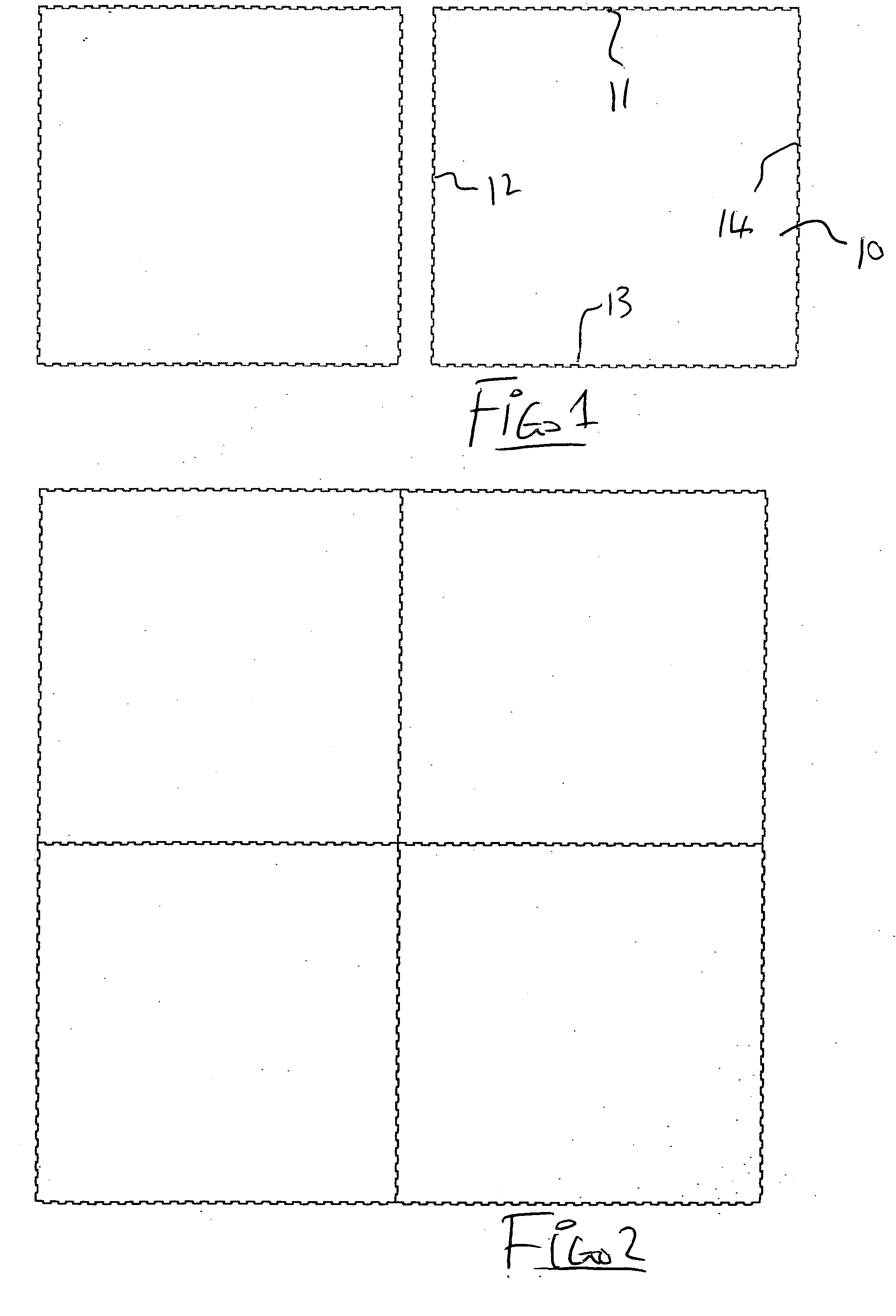
[0053]In FIGS. 1 and 2 is shown a series of the panels of the present invention each of which is rectangular, preferably square, in plan to form four side edges. Thus the panel is indicated at 10 and includes side edges 11, 12, 13 and 14. In FIG. 1 the panels are arranged side by side ready to be connected edge to edge. In FIG. 2 the panels are shown in plan view with four of the panels connected edge to edge to form an array of the panels which defines a part of a floor covering to cover an existing substrate.

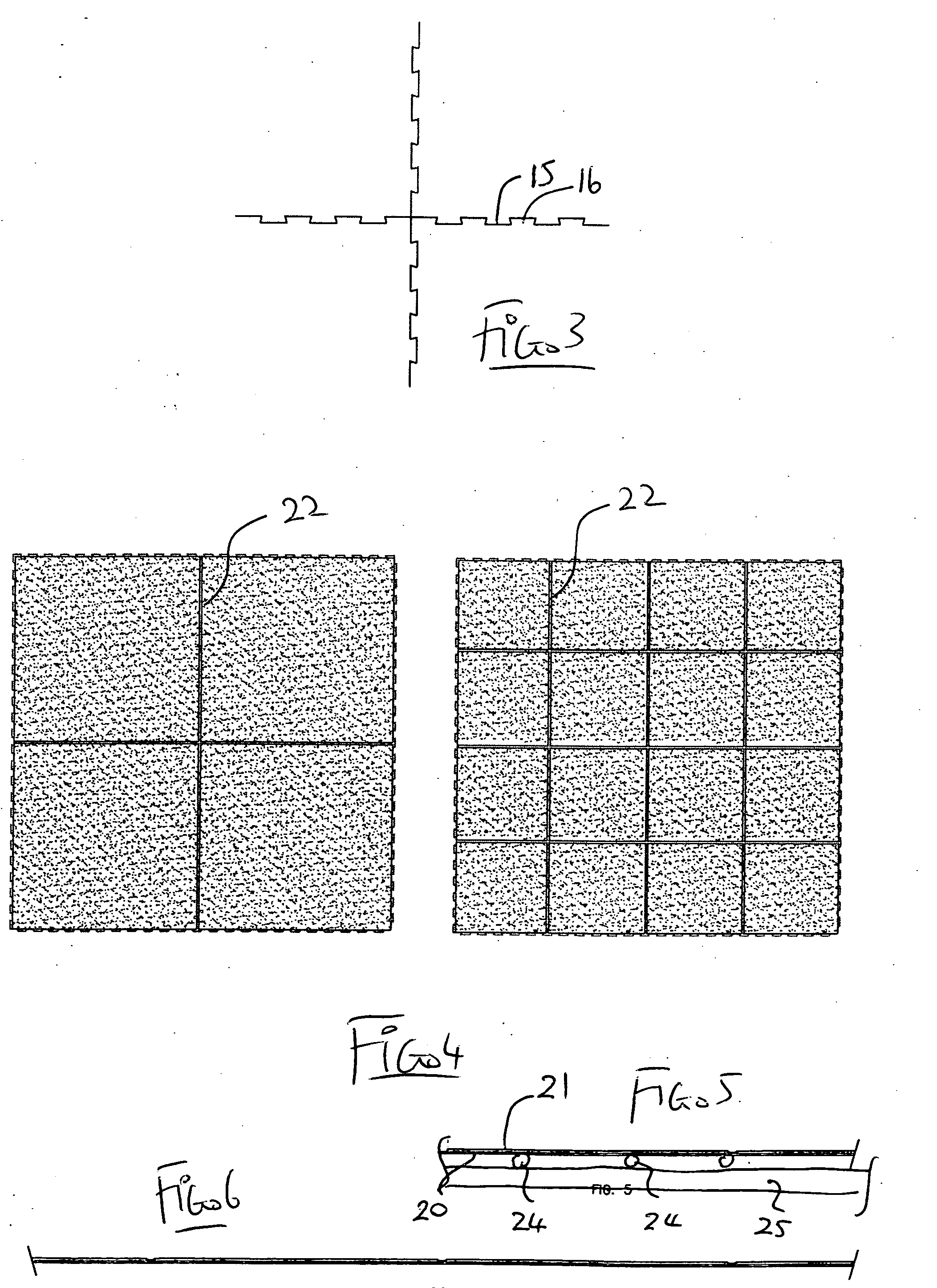
[0054]FIG. 3 shows an enlarged view of the edges of the panels at a junction between four of the panels so that the projections and recesses can be seen in more detail. Thus at the side edges of the panels there are provided recesses 15 and projections 16 arranged side by side in a castellated manner along the side edge. The projections are relatively small having a distance from the side edge only of the order of ⅛ to ¼ inch. The tiles are symmetrical at the corners which all...


PUM


Abstract

A metal-stone floor or wall covering, more particularly a “hard surface” floor covering is created in plant by stamping large panels from sheet metal with an interlocking reversing notched edge. This allows each large panel to lock into additional panel sufficient to cover a floor area, whereupon the sheet metal in plant is covered with cross linking polymer cement mixed with crushed powdered stone and the resulting slurry is applied over the surface of the sheet metal in a thin layer and allowed to harden. Grout line grooves are carved into the mixed overlay and filled with a latex grout which is then allowed to harden after which, the tile is colorized, and then sealed with a clear coat, dried and shipped to site for bonding in place by beads of a foamed adhesive which allow some flexing of the floor as an integral structure.

Description

[0001]This invention relates to a floor or wall covering material and particularly a floor and wall covering material arranged to simulate ceramic, porcelain or stone tile.BACKGROUND OF THE INVENTION[0002]In recent years, laminate floors have simplified and have improved the efficiency of the installation of real and simulated hardwood floors. However, ceramic and porcelain and stone tile flooring has changed very little and while the marketplace desires hard surface floor coverings that are attractive and durable, ceramic and porcelain are by nature heavy, hard and brittle, time consuming to install and require extensive surface preparation for installation. In addition when it comes to changing the floor covering the process of removing ceramic and porcelain and stone is messy and time consuming.SUMMARY OF THE INVENTION[0003]It is one object of the invention to provide an improved floor or wall covering material which simulates tile.[0004]According to one aspect of the invention t...

Claims


Application Information

Patent Timeline
Patent Type & Authority Applications(United States)
IPC IPC(8): B44F7/00
CPCB44C3/123E04F11/1045E04F13/147E04F11/112E04F2201/091E04F2201/095E04F2290/023E04F15/02Y02B30/00
Inventor DOMBOWSKY, MICHAEL
Owner DOMBOWSKY MICHAEL
Why Eureka
Try Eureka