Turbine engine with an alternator and method for transmitting movement to an alternator

a turbine engine and alternator technology, applied in the direction of machines/engines, mechanical equipment, electric generator control, etc., can solve the problems of high risk of hp compressor pumping, high installation cost, heavy gearbox, etc., and achieve the effect of simple installation

Active Publication Date: 2008-01-10
SN DETUDE & DE CONSTR DE MOTEURS DAVIATION S N E C M A
View PDF15 Cites 37 Cited by
  • Summary
  • Abstract
  • Description
  • Claims
  • Application Information

AI Technical Summary

Benefits of technology

[0010]The object of the invention is to propose a turbine engine with a device for driving the alternator that is simpler to install and lighter than a gearbox, while allowing a drive of the alternator in which the proportion of power taken from the HP body at low speed is not too great in comparison with the power taken from the LP body.

Problems solved by technology

The risks of pumping of the HP compressor are therefore great.
However, such a gearbox is extremely heavy and costly to install and requires a particular electro-hydraulic controller.

Method used


Image

  • Turbine engine with an alternator and method for transmitting movement to an alternator
  • Turbine engine with an alternator and method for transmitting movement to an alternator
  • Turbine engine with an alternator and method for transmitting movement to an alternator

Examples


Embodiment Construction

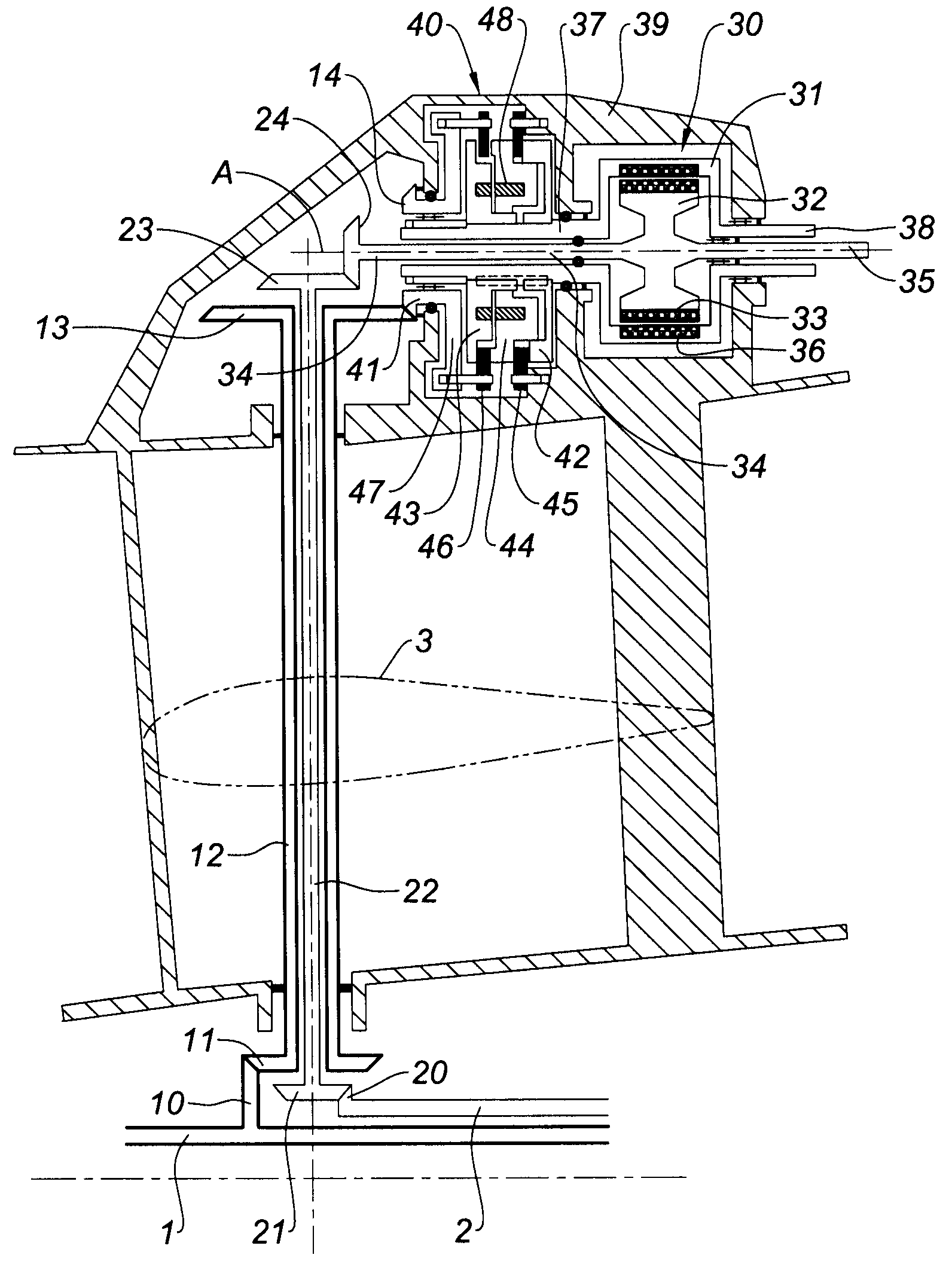
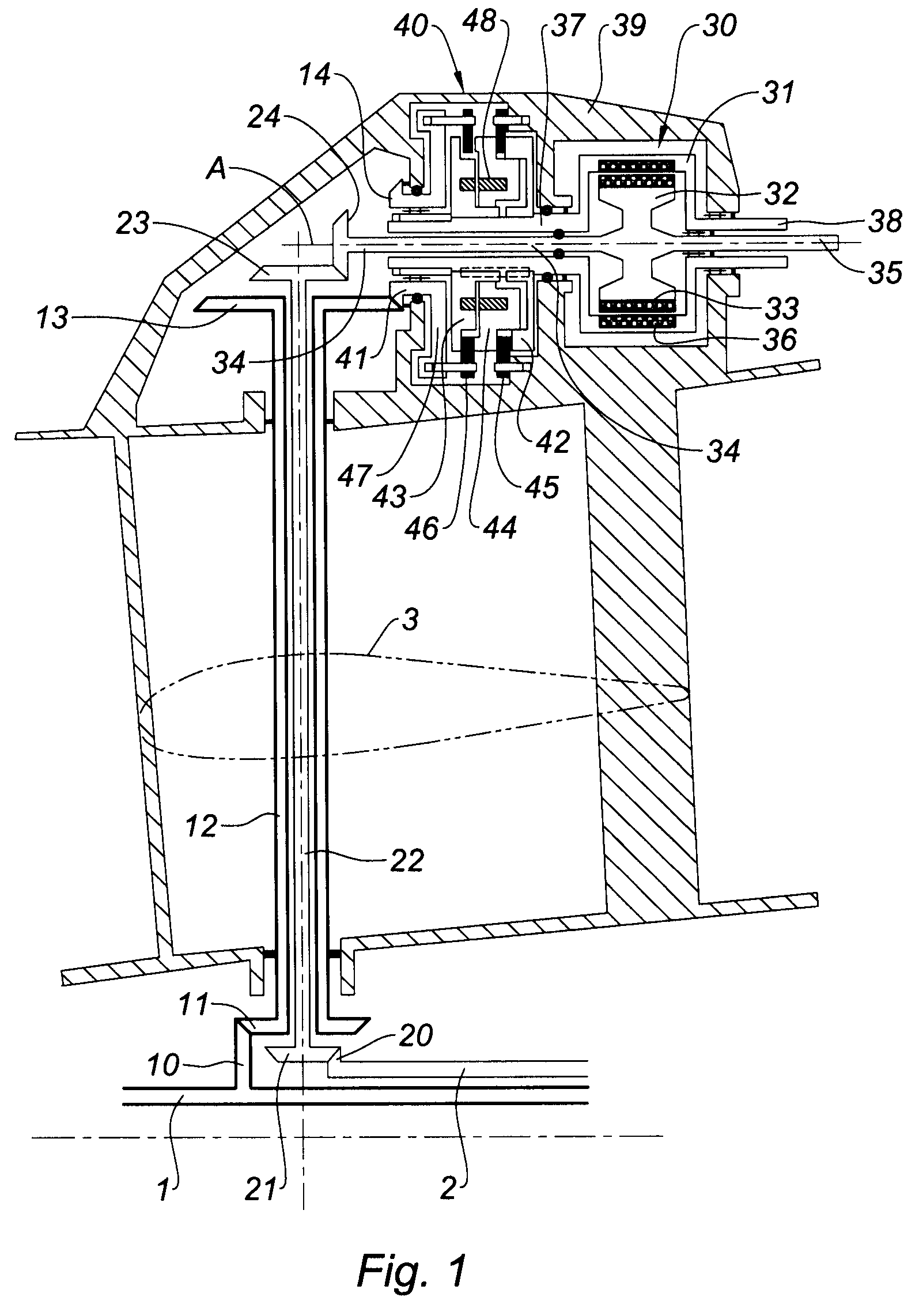
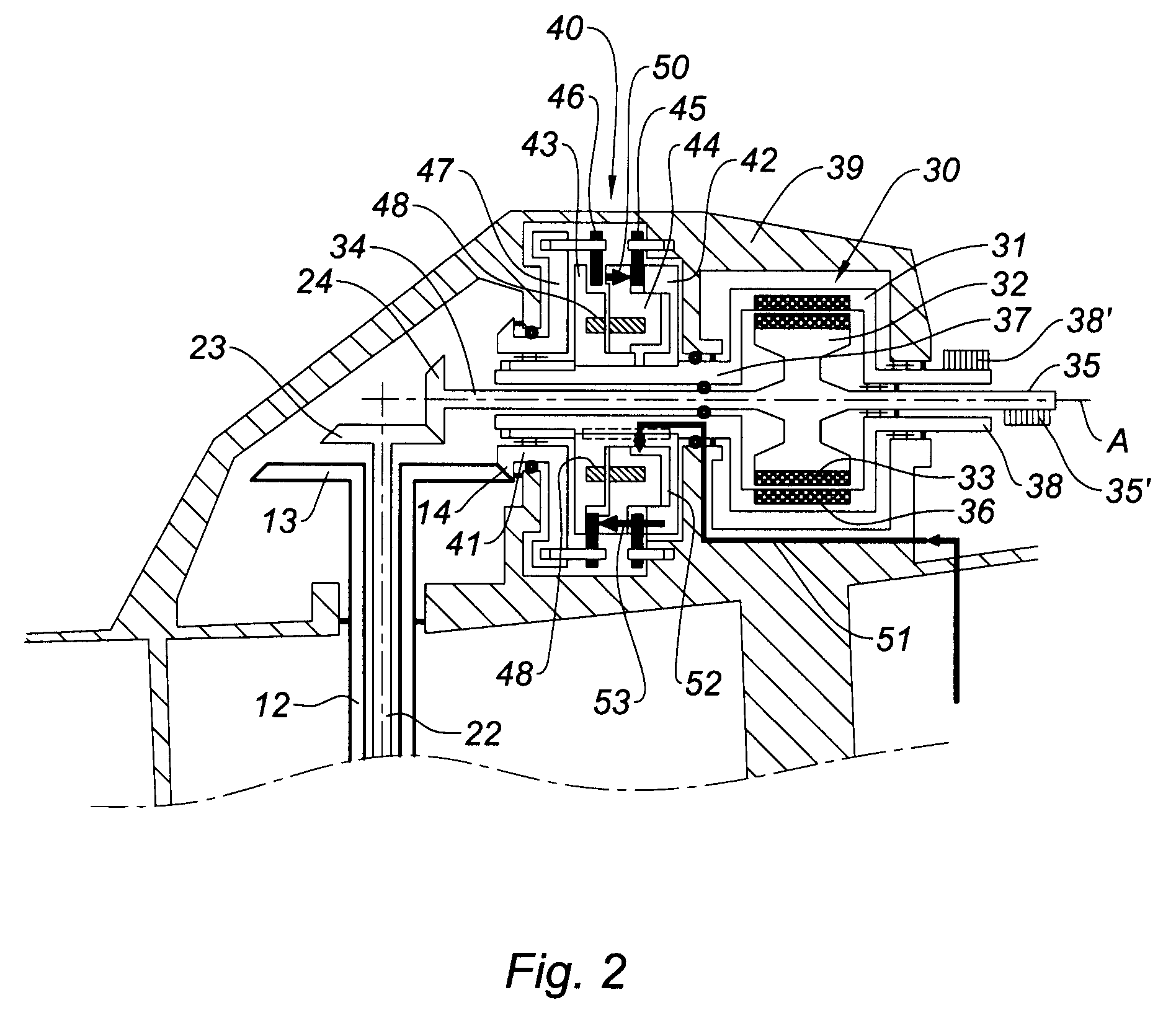
[0025]With reference to these FIGS. 1 and 2, the turbine engine of the invention is a twin-spool turbine engine comprising a low-pressure (LP) rotor 1 and a high-pressure (HP) rotor 2. This type of turbine engine is well known to those skilled in the art. In this instance it is a turbojet. In fact it is any turbine engine comprising a compressor and a turbine, twin-spool, with a low-pressure body and a high-pressure body. Each of the rotors 1, 2 comprises, at its periphery, longitudinally approximately at the structural arms of the intermediate casing of the turbojet, a bevel gear 10, 20, respectively. The gear 20 of the HP rotor 2 is situated at the upstream end of the HP rotor, the gear 10 of the LP rotor 1 being situated just upstream of this end. The intermediate casing is a structural casing, of which an outer shroud is situated in the extension and downstream of the fan casing, comprising structural arms and being in particular the casing to which the pylon is attached for ups...


PUM


Abstract

The turbine engine of the invention is a twin-spool turbine engine, comprising a low-pressure rotor (1) and a high-pressure rotor (2), an alternator (30), comprising an inductor winding (32) and an armature (31), the high-pressure rotor (2) rotating the inductor winding (32) of the alternator (30). The armature (31) is mounted so as to rotate and the low-pressure rotor (1) is connected to clutch means (40) arranged so that the low-pressure rotor (1) drives the armature (31) in a manner that is contrarotational to the inductor winding (32) when the clutch means (40) are engaged.
Thanks to the invention, the power for the alternator is taken off in a manner distributed between the LP rotor and the HP rotor.

Description

BACKGROUND OF THE INVENTION[0001]A portion of the power generated by an aviation turbine engine is used for supplying various members of the turbine engine but also of the aircraft whose turbine engine participates in the propulsion.[0002]A portion of this power is currently taken off at the high-pressure compressor, whose compressed air is used particularly for pressurizing and air conditioning the aircraft cabin, or else deicing. Another portion of this power is taken off mechanically from the shaft of the high-pressure (HP) body of the turbine engine, in order to drive the input shaft of an accessory gearbox. This input shaft is rotated by a transmission shaft extending in a structural arm of the casing and itself driven by a gear fixedly attached to the HP shaft.[0003]The accessory gearbox (AGB), well known to those skilled in the art, comprises various machines, or accessories, for example an electric generator, a starter, an alternator, hydraulic, fuel or oil pumps, etc. These...

Claims


Application Information

Patent Timeline
Patent Type & Authority Applications(United States)
IPC IPC(8): F02K3/02
CPCF02C7/32Y02T50/671H02K16/005Y02T50/60
Inventor LARDELLIER, ALAIN MARIE JOSEPH
Owner SN DETUDE & DE CONSTR DE MOTEURS DAVIATION S N E C M A
Why Eureka
Try Eureka