
Electronically controlled frequency dependent damping

a frequency dependent damping and electromagnetic control technology, applied in the direction of shock absorbers, mechanical equipment, transportation and packaging, etc., can solve the problems of complex systems developed to produce hydraulic liquid filled shock absorbers, lack of ability to change damping characteristics in response, and inability to achieve the effect of damping characteristics

Inactive Publication Date: 2008-01-10
TENNECO AUTOMOTIVE OPERATING CO INC
View PDF66 Cites 76 Cited by
  • Summary
  • Abstract
  • Description
  • Claims
  • Application Information

AI Technical Summary

Benefits of technology

The present invention is a gas or air damper that can adjust its damping based on the vehicle's operating parameters. This allows for an optimal shock absorber performance for the current conditions. The invention can be used in various vehicles and can improve their overall performance.

Problems solved by technology

While meeting with success in the automotive industry, hydraulic liquid filled shock absorbers are not without problems.
One problem associated with the prior art hydraulic liquid shock absorbers is their lack of ability to change the damping characteristics in response to the frequency of vibration.
In order to overcome this deficiency, complex systems have been developed to produce hydraulic liquid filled shock absorbers which are relatively soft for high frequency vibrations while being relatively stiff for low frequency vibrations.
Other problems associated with the prior art hydraulic liquid filled shock absorbers include the variability in their damping forces due to the temperature changes of the hydraulic liquid.
In addition, any aeration of the hydraulic liquid during operation adversely affects the operation of the damper due to the introduction of a compressible gas into the non-compressible hydraulic liquid.
Finally, the hydraulic liquid adds to the weight of the shock absorber as well as presenting environmental concerns regarding the use of the hydraulic liquid.

Method used


Image

  • Electronically controlled frequency dependent damping
  • Electronically controlled frequency dependent damping
  • Electronically controlled frequency dependent damping

Examples


Embodiment Construction

[0021] The following description of the preferred embodiment(s) is merely exemplary in nature and is in no way intended to limit the invention, its application, or uses.

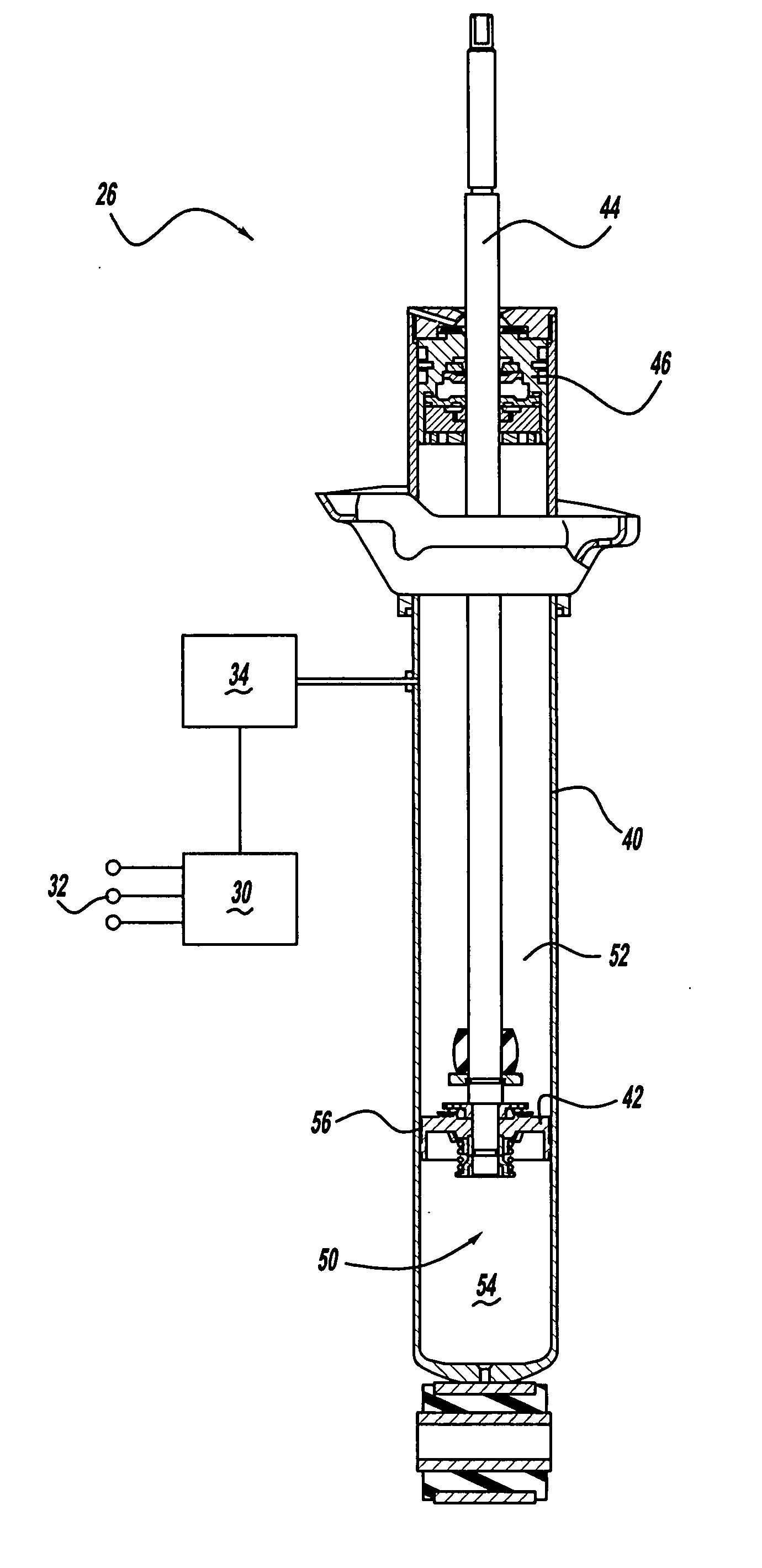
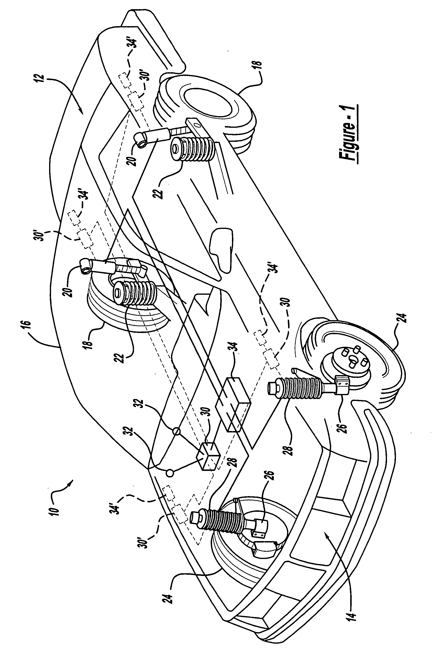
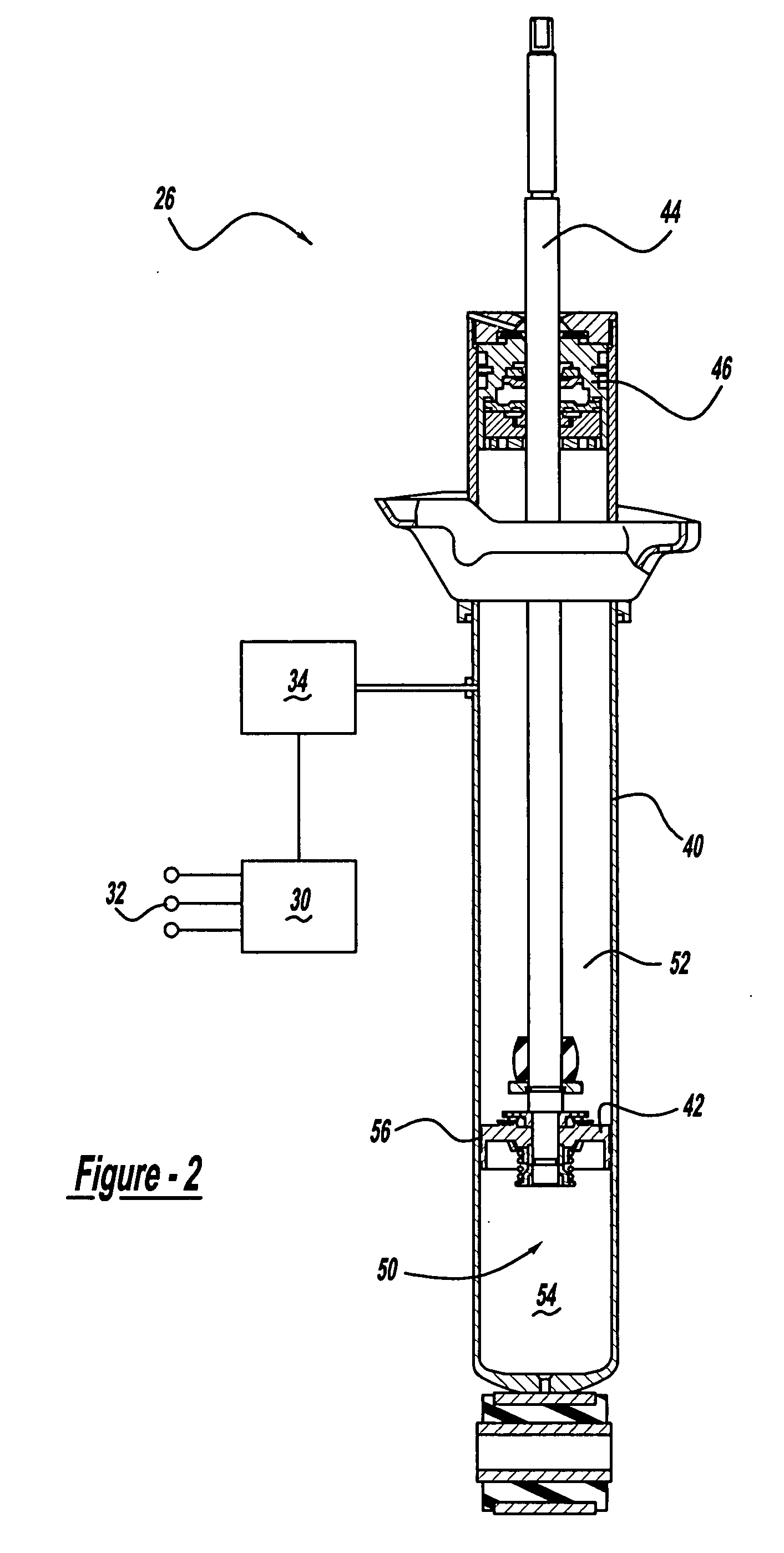
[0022] Referring now to the drawings in which like reference numerals designate like or corresponding parts throughout the several views, there is shown in FIG. 1 a vehicle incorporating a suspension system having the electronically controlled frequency dependent dampers in accordance with the present invention which is designated generally by the reference numeral 10. Vehicle 10 includes a rear suspension 12, a front suspension 14 and a body 16. Rear suspension system 12 includes a pair of independent suspensions adapted to operatively support a pair of rear wheels 18. Each rear independent suspension is attached to body 16 by means of a shock absorber 20 and a helical coil spring 22. Similarly, front suspension 14 includes a pair of independent suspensions adapted to operatively support a pair of front wheels 24. ...


PUM


Abstract

A gas damper includes a gas pressurized working chamber and valving within the piston to control flow of the gas through the piston. A system is in communication with the working chamber to control the gas pressure within the working chamber in order to control the damping characteristics of the damper. An electronic control unit is utilized to control the opening and closing of the valving within the piston to also control the damping characteristics of the damper.

Description

CROSS-REFERENCE TO RELATED APPLICATIONS [0001] This application is a divisional of U.S. patent application Ser. No. 10 / 775,880 filed on Feb. 10, 2004. The disclosure of the above application is incorporated herein by reference.FIELD OF THE INVENTION [0002] The present invention relates generally to dampers or shock absorbers adapted for use in a suspension system such as the suspension system used for automotive vehicles. More particularly, the present invention relates to a shock absorber which utilizes a gas rather than hydraulic fluid as the damping medium and electronic controls which adjust the damping characteristics of the shock absorber based upon inputs from one or more sensors. BACKGROUND OF THE INVENTION [0003] Shock absorbers are used in conjunction with automotive suspension systems to absorb unwanted vibrations which occur during driving. To absorb the unwanted vibrations, shock absorbers are generally connected between the sprung portion (body) and the unsprung portio...

Claims


Application Information

Patent Timeline
Patent Type & Authority Applications(United States)
IPC IPC(8): F16F9/00F16F5/00
CPCB60G17/0152B60G17/0416B60G2500/10B60G2400/206B60G2400/91B60G17/08F16F9/50F16F9/512F16F9/516
Inventor VANDEWAL, BART
Owner TENNECO AUTOMOTIVE OPERATING CO INC
Learn More