Fuel injector with injection rate control

a fuel injector and injection rate technology, applied in the direction of fuel injecting pumps, liquid fuel feeders, machines/engines, etc., can solve the problems of increasing the control volume pressure, increasing the size and complexity of the injector, increasing the cost, and increasing the size of the injector, so as to improve the brake specific fuel consumption reduce the nitrous oxide, and reduce the noise of combustion

Active Publication Date: 2008-01-10
CUMMINS INC
View PDF36 Cites 9 Cited by
  • Summary
  • Abstract
  • Description
  • Claims
  • Application Information

AI Technical Summary

Benefits of technology

[0013] One advantage of the present invention is in providing a cost effective, efficient, flexible and responsive injector and method of controlling fuel injection rate.
[0014] Another advantage of the present invention is in producing a commercially viable system to produce multiple fuel injection mass flow rates from a common source of pressurized fuel.
[0015] Yet another advantage of the present invention is in being compatible with existing fuel systems.
[0016] A still further advantage of the present invention is in providing a wide variety of rate shape choices.
[0017] Still another advantage of the present invention is to provide a fuel injector and fuel system capable of reducing nitrous oxides, particulates and combustion noise while also improving brake specific fuel consumption.
[0018] The above advantages and other advantages are achieved by providing the closed nozzle fuel injector of the present invention for injecting fuel at high pressure into the combustion chamber of an engine, comprising an injector body containing an injector cavity and an injector orifice communicating with one end of the injector cavity to discharge fuel into the combustion chamber. The injector also includes a fuel transfer circuit at least partially formed in the injector body to deliver supply fuel to the injector orifice, wherein the fuel transfer circuit including a first circuit and a second circuit in parallel with the first circuit. The injector also includes a nozzle valve element positioned in the injector cavity adjacent the injector orifice. The nozzle valve element is movable between an open position in which fuel may flow through the injector orifice into the combustion chamber and a closed position in which fuel flow through the injector orifice is blocked. Importantly, the injector includes a rate shaping sleeve mounted on the nozzle valve element for movement between a first position blocking flow through the second circuit and a second position permitting flow through the second circuit. The rate shaping sleeve includes a valve surface positioned in sealing contact with the nozzle valve element when the rate shaping sleeve is in the first position to block flow through the second circuit.

Problems solved by technology

Opening of the injection control valve causes a reduction in the fuel pressure in the control volume resulting in a pressure differential which forces the needle valve open, and closing of the injection control valve causes an increase in the control volume pressure and closing of the needle valve.
Moreover, the use of a separate expandable chamber device mounted on or near an injector increases the costs, size and complexity of the injector.

Method used


Image

  • Fuel injector with injection rate control
  • Fuel injector with injection rate control
  • Fuel injector with injection rate control

Examples


Embodiment Construction

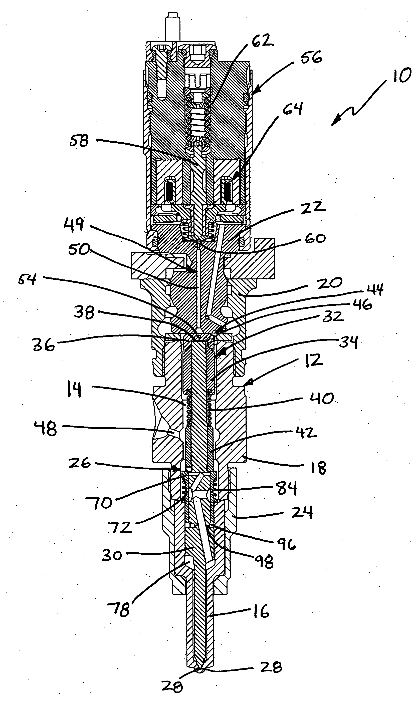
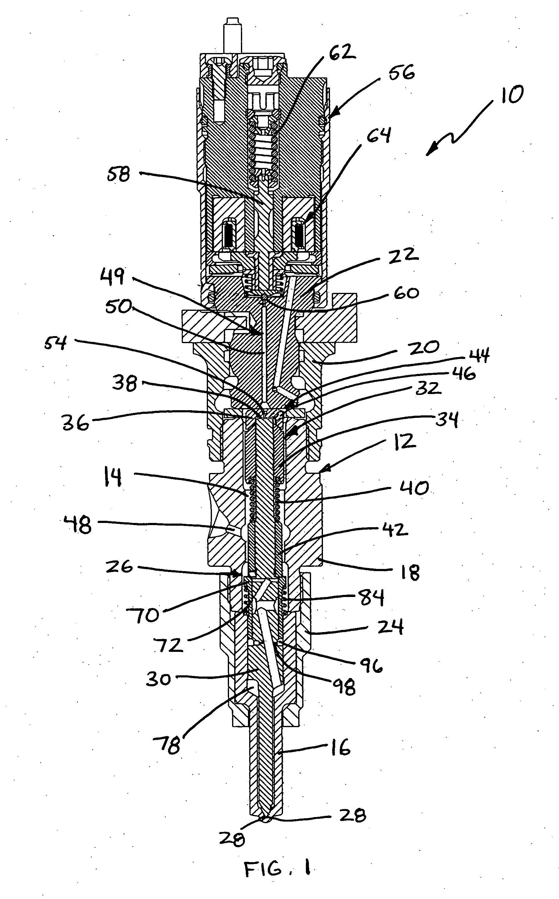
[0032] Referring to FIG. 1, there is shown an exemplary embodiment of the closed nozzle fuel injector of the present invention, indicated generally at 10, which functions to effectively control the fuel injection flow rate, especially during an initial portion of an injection event, while also permitting accurate control over pilot and / or post injection events and flow quantities at all operating conditions thereby ultimately advantageously reducing emissions and combustion noise while improving brake specific fuel consumption. Closed nozzle injector 10 is generally comprised of an injector body 12 having a generally elongated, cylindrical shape which forms an injector cavity 14. The injector body 12 includes a cup 16, an inner barrel 18, an outer barrel 20, a support 22 and a retainer 24. Retainer 24 threadably engages inner barrel 18 to hold cup 16 and inner barrel 18 in a compressive abutting relationship by simple relative rotation of retainer 24 and inner barrel 18. Outer barre...


PUM


Abstract

A closed nozzle fuel injector is provided which effectively controls the fuel injection flow rate, especially during an initial portion of an injection event, while also permitting accurate control over pilot and / or post injection flow rates at all operating conditions thereby advantageously reducing emissions and combustion noise. The injector includes a rate shaping orifice to restrict fuel flow during an initial portion of an injection event and a rate shaping sleeve mounted for movement to cause a greater flow of injection fuel during a later portion of the injection event. A damping chamber and orifice are also provided to control movement of the rate shaping sleeve.

Description

BACKGROUND OF THE INVENTION [0001] 1. Technical Field [0002] This invention relates to an improved fuel injector which effectively controls the flow rate of fuel injected into the combustion chamber of an engine. [0003] 2. Description of Related Art [0004] In most fuel supply systems applicable to internal combustion engines, fuel injectors are used to direct fuel pulses into the engine combustion chamber. A commonly used injector is a closed-nozzle injector which includes a nozzle valve assembly having a spring-biased nozzle or needle valve element positioned adjacent the needle orifices for resisting blow back of exhaust gas into the pumping or metering chamber of the injector while allowing fuel to be injected into the cylinder. The needle valve element also functions to provide a deliberate, abrupt end to fuel injection thereby preventing a secondary injection which causes unburned hydrocarbons in the exhaust. The needle valve element is positioned in a nozzle cavity and biased ...

Claims


Application Information

Patent Timeline
Patent Type & Authority Applications(United States)
IPC IPC(8): F02D1/06
CPCF02M45/083F02M47/027F02M2200/315F02M63/0017F02M61/042F02M63/0022
Inventor BENSON, DONALD J.RIX, DAVID M.PETERS, LESTER L.VENKATARAMAN, SHANKAR C.MORRIS, C. EDWARD JR.
Owner CUMMINS INC
Why Eureka
Try Eureka