Flat screen

a technology of flat screen and light source, which is applied in the field of flat screen, can solve the problems of considerable heat development, reduced integrated brightness of the screen, and high assembly cost, and achieve the effects of reducing the number of individual point light sources and/or leds, reducing the cost of assembly, and increasing the production cos

Inactive Publication Date: 2008-01-10
NANOGATE ADVANCED MATERIALS
View PDF12 Cites 8 Cited by
  • Summary
  • Abstract
  • Description
  • Claims
  • Application Information

AI Technical Summary

Benefits of technology

[0009] It is particularly preferred to configure the individual surface elements such that the amplitude of the different surface structures is constant and only the frequency is changed. This ensures that the diffraction efficiency is constant across the overall cross-section. Depending on the type of surface structure, which must not necessarily by a sinusoidal surface structure, all raised portions are, more generally expressed, of equal height but are arranged at different distances to each other. Consequently, the light emitted by the light source is diffracted in different ways by the individual surface elements. It is of particular advantage that varying distances are easier to produce than varying heights.
[0010] Provision of a light-guiding element comprising a plurality of surface elements, which are arranged at the surface according to the invention, allows the number of the individual point light sources and / or LEDs to be considerably reduced. At constant brightness distribution and constant effective brightness of the flat screen, the number of LEDs can be reduced by more that 10%, and in particular more than 40%.

Problems solved by technology

The use of such films has the drawback that the films absorb a portion of the light such that the integral brightness of the screen is reduced.
This entails considerable costs and a high assembly effort.
Further, the large number of LEDs leads to a considerable heat development.

Method used


Image

  • Flat screen
  • Flat screen
  • Flat screen

Examples


Embodiment Construction

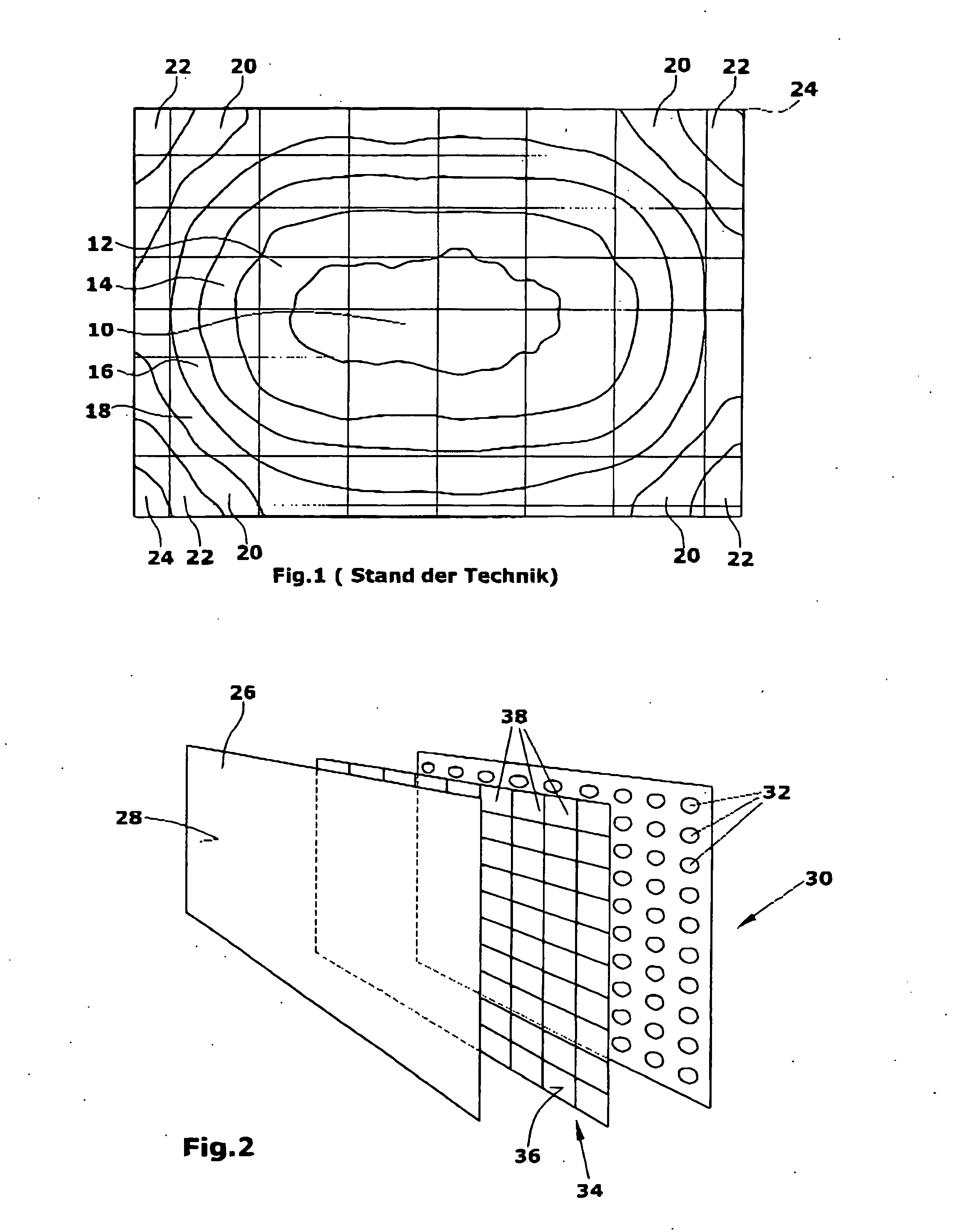
[0035] The diagram of FIG. 1 schematically shows a brightness distribution of an LCD screen. Said screen is an LCD screen backlit by LEDs, wherein in prior art a BEF film and a DBEF film are provided between the LEDs and the LCD screen for the purpose of rendering the illumination more uniform. In the diagram the brightness is largest in an inner region 10 and decreases essentially concentrically in outward direction in the regions 12,14,16,18. The darkest regions occur in the corners, wherein here, too, the brightness decreases from the regions 20 via the regions 22 towards the regions 24.

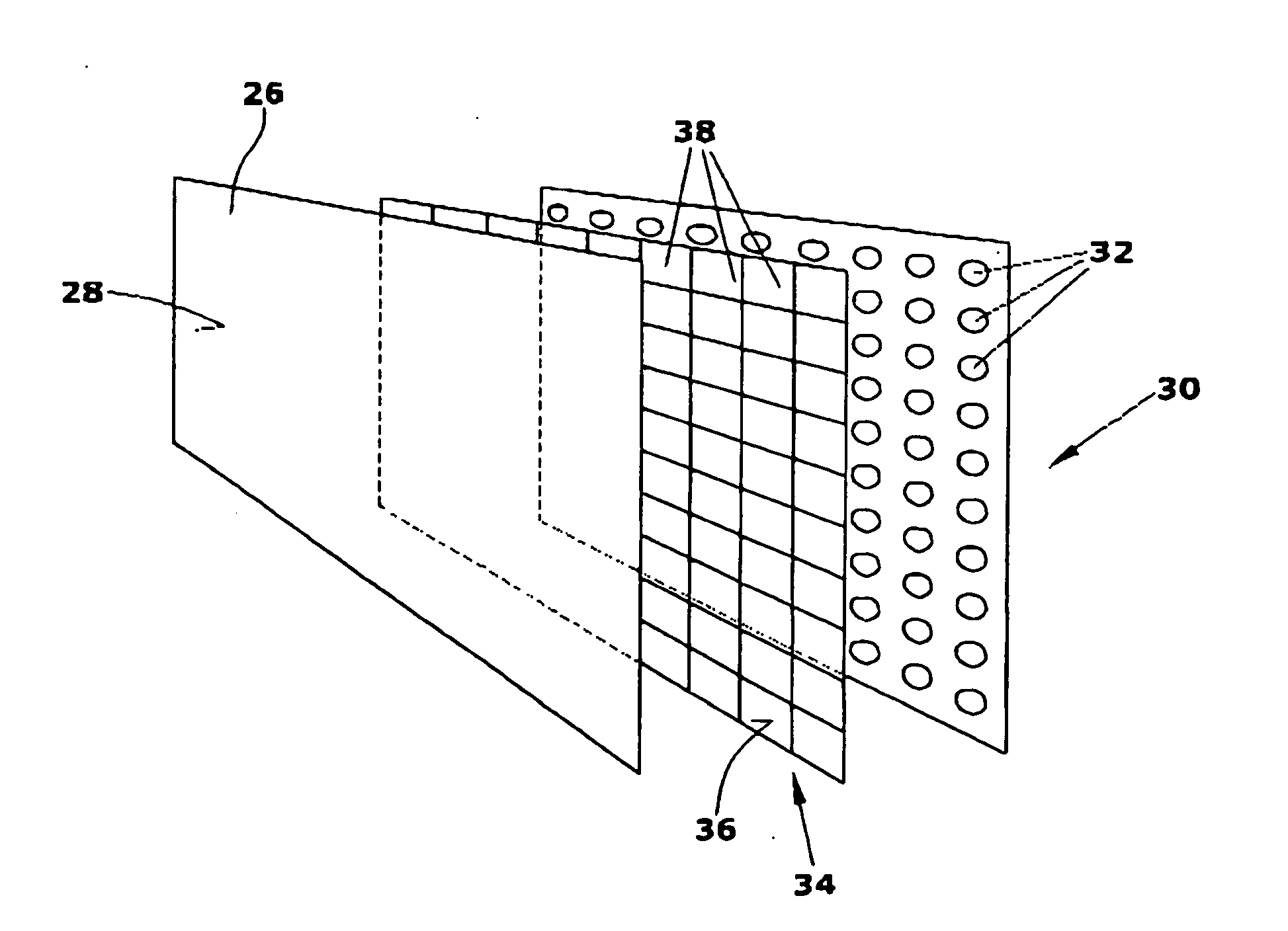
[0036] An LCD flat screen according to the invention (FIG. 2) comprises an LCD element and / or a liquid-crystal element 26 on whose front side 28 the image is represented. In a light box and / or illuminating element 30 a plurality of point light sources in the form of LEDs 32 are arranged. In the illustrated embodiment, said LEDs 32 are arranged at a regular mutual distance of 10 mm.

[0037] Accordi...


PUM

PropertyMeasurementUnit
distanceaaaaaaaaaa
distanceaaaaaaaaaa
distanceaaaaaaaaaa

Abstract

A flat screen comprises a liquid-crystal element, such as an LCD element, for representing an image. Further, a plurality of point light sources, such as LEDs, are provided. Between the point light sources and the liquid-crystal element a light-guiding element is arranged. For rendering the brightness distribution more uniform, the light-guiding element comprises at a surface thereof a plurality of diffractive surface elements arranged in cells.

Description

CROSS REFERENCE TO RELATED APPLICATIONS [0001] This application claims priority to European patent application No. 05 005 249.1 filed on Mar. 10, 2005, and to U.S. provisional patent application No. 60 / 691,717 filed Jun. 17, 2005, which applications are hereby incorporated by this reference in their entireties.BACKGROUND OF THE INVENTION [0002] The invention relates to a flat screen, and in particular to an LCD screen lit by LEDs. [0003] Known screens with liquid-crystal elements comprise an illuminating element, such as a light box, in which a plurality of fluorescent tubes, in particular CCFLs, are arranged. To render the illumination of the liquid-crystal element more uniform, light-guiding elements are arranged between the illuminating element, i.e. the tubes, and the liquid-crystal element. These light-guiding elements are films designated BEF, DBEF and PRF. For the purpose in question, the BEF film has a surface comprising a plurality of small prisms. These prisms are refracti...

Claims


Application Information

Patent Timeline
Patent Type & Authority Applications(United States)
IPC IPC(8): G02F1/1335
CPCG02F2203/22G02F1/133603G02F1/1335
Inventor KLENKE, MARTIN
Owner NANOGATE ADVANCED MATERIALS
Why Eureka
Try Eureka