Reserved Record Display System, Reserved Display Device, Reserved Record Display Method, Program, and Recording Medium

a timer recording and display system technology, applied in the field of reserved record display system, can solve the problems that the program that a user desires to subject to timer recording cannot be received by the tuner contained in the pvr, and it is disadvantageously not easy to determine which home appliances are to cooperate in timer recording, and achieve the effect of easy determination

Inactive Publication Date: 2008-01-10
PANASONIC CORP
View PDF4 Cites 11 Cited by
  • Summary
  • Abstract
  • Description
  • Claims
  • Application Information

AI Technical Summary

Benefits of technology

[0057] The present invention has the advantage of, when a plurality of home network-compatible timer recording appliances ar

Problems solved by technology

Under these circumstances, programs that a user desires to subject to timer recording cannot be received by a tuner contained in a PVR.
This results in the need to execute timer recording of outputs from a separate dedicated set

Method used


Image

  • Reserved Record Display System, Reserved Display Device, Reserved Record Display Method, Program, and Recording Medium
  • Reserved Record Display System, Reserved Display Device, Reserved Record Display Method, Program, and Recording Medium
  • Reserved Record Display System, Reserved Display Device, Reserved Record Display Method, Program, and Recording Medium

Examples


embodiment 1

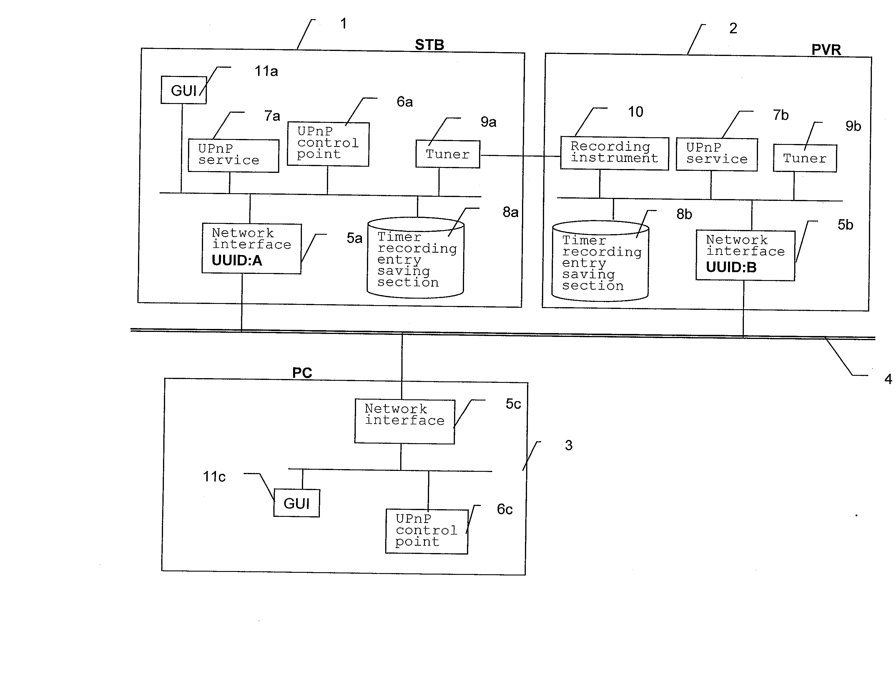
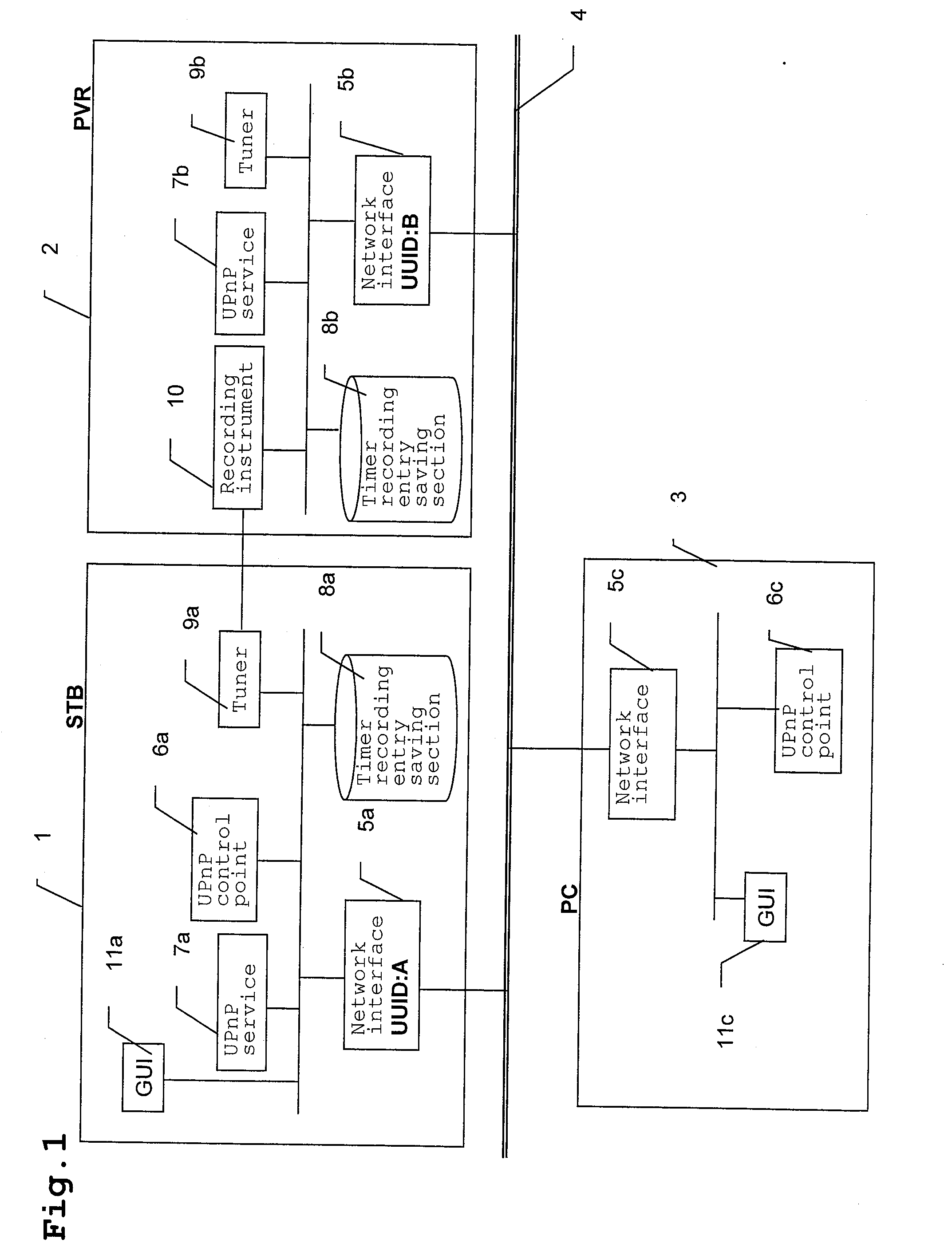
[0097] First, with reference mainly to FIG. 1, a block diagram of a timer recording system in accordance with Embodiment 1 of the present invention, description will be given of configuration of a timer recording system in accordance with the present embodiment.

[0098] Reference numeral 1 denotes a set top box (hereinafter referred to as an STB), and reference numeral 2 denotes a personal video recorder (hereinafter referred to as a PVR) utilizing a hard disk. Reference numeral 3 denotes a personal computer (hereinafter referred to as a PC), and reference numeral 4 denotes a home network. Reference numerals 5a, 5b, and 5c denote network interfaces to which the STB 1, PVR 2, and PC 3, respectively, can be coupled via the home network 4. Reference numerals 6a and 6c denote UPnP control points in accordance with the UPnP which constitute the STB 1 and PC 3. Reference numerals 7a and 7b denote UPnP services that provide timer recording services in accordance with the UPnP. Reference num...

embodiment 2

[0134] Now, description will be given of the configuration and operation of a timer recording system in accordance with Embodiment 2.

[0135] The configuration of the present embodiment is the same as that of Embodiment 1 (see FIG. 1), described above, except for timings for generating timer recording entries.

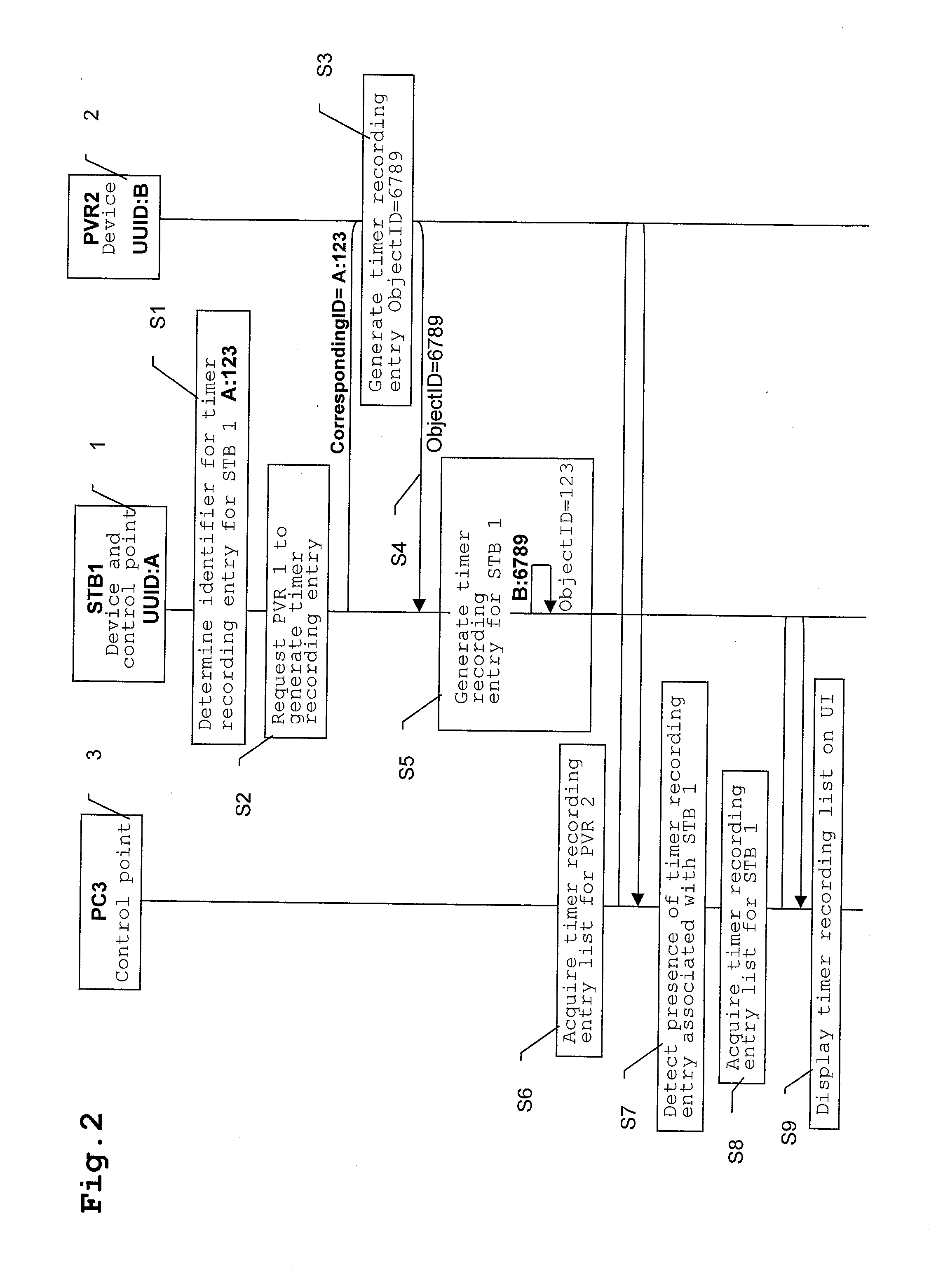
[0136] Thus, the operation of the present embodiment will be described with reference mainly to FIG. 1 and FIG. 4, a diagram illustrating the operation of the timer recording system in accordance with Embodiment 2 of the present invention.

[0137] The user is operating the STB 1 while viewing the GUI 11a. The user is to execute timer recording of a certain broadcast program. Since this broadcast program is terrestrial digital, it cannot be recorded by means of the built-in tuner 9b in the PVR 2. Thus, the user decides to input reception outputs from the STB 1 to the PVR 2 for recording. The user programs the tuner 9a so that the STB 1 starts receiving the broadcast channel of th...

embodiment 3

[0159] Now, description will be given of configuration and operation of a timer recording system in accordance with Embodiment 3.

[0160]FIG. 5 is a block of the timer recording system in accordance with Embodiment 3 of the present invention. The STB 1, PVR 2, and PC 3 are the same as those in accordance with Embodiments 1 and 2, described above, and will thus not be described. Reference numeral 3b denotes a PC, and reference numeral 5d constituting the PC 3b denotes a network interface. Reference numeral 6d denotes a UPnP control point, and reference numeral 11d denotes a GUI.

[0161] Thus, the operation of the present embodiment will be described with reference mainly to FIG. 5 and FIG. 6, a diagram illustrating the operation of the timer recording system in accordance with Embodiment 3 of the present invention.

[0162] The user is setting a certain broadcast program to be subjected to timer recording by operating the STB 1 and PVR 2 via the home network 4 while viewing the GUI 11a. ...


PUM


Abstract

The present invention provides a timer recording system including a PVR having a unique UUID and executing timer recording of a program set, an STB having a unique UUID and holding a timer recording entry in a timer recording entry saving section, the timer recording entry describing at least the UUID of the PVR controlled by the STB and timer recording information for executing the timer recording of the set program, the STB controlling the PVR on the basis of the timer recording entry held by the STB, and a PC that provides display for a combination of the UUID of the PVR executing the timer recording of the set program, the UUID of the STB controlling the PVR executing the timer recording, and the timer recording information for executing the timer recording of the set program.

Description

TECHNICAL FIELD [0001] The present invention relates to a timer recording display system, a timer recording display device, a timer recording display method, a program, and a recording medium which can be utilized for timer recording using a plurality of home network-compatible timer recording appliances. BACKGROUND ART [0002] A protocol called Universal Plug and Play (hereinafter referred to as UPnP) has been standardized to enable detection and control of appliances coupled to a network (see, for example, Japanese Patent Laid-Open No. 2004-228849, and Microsoft Corporation, “Universal Plug and Play Device Architecture”, [online], UPnP Forum, 10:41 a.m., Jun. 8, 2000, [searched on Aug. 24, 2004], Version 1.0, Internet <URL:http: / / www.upnp.org / download / UPnPDA10—20000613. htm>). The entire disclosure of Japanese Patent Laid-Open No. 2004-228849 and “Universal Plug and Play Device Architecture” is incorporated herein by reference in its entirety. [0003] The UPnP uses the standar...

Claims


Application Information

Patent Timeline
IPC IPC(8): H04N5/91
CPCG11B27/11H04L67/125G11B2220/412H04L12/2812H04L29/12801H04L61/1582H04L61/6004H04N5/765H04N5/775H04N5/781H04N5/782H04N21/4135H04N21/4147H04N21/43615H04N21/47214G11B27/34H04L2101/604H04L61/457G11B20/10H04N5/76G11B27/00
Inventor HORI, MASATOMO
Owner PANASONIC CORP
Why Eureka
Try Eureka