Method of error correction in a multi-bit-per-cell flash memory

a multi-bit per-cell, flash memory technology, applied in the direction of information storage, instruments, electric digital data processing, etc., can solve the problems of reducing performance, mbc flash is less reliable than sbc, and the drawbacks of using mbc flash

Inactive Publication Date: 2008-01-10
RAMOT AT TEL AVIV UNIV LTD
View PDF7 Cites 168 Cited by
  • Summary
  • Abstract
  • Description
  • Claims
  • Application Information

AI Technical Summary

Benefits of technology

[0027]One conceptual innovation of the present invention is that, contrary to the conventional wisdom, iterative decoding is of practical use, not only in communication, but also in data storage. For example, iterative decoding of data stored in a flash memory device makes storing three or more bits per cell in the memory of such a device commercially viable.

Problems solved by technology

However, there are drawbacks to using MBC flash.
Average read and write times of MBC memories are longer than of SBC memories, resulting in reduced performance.
More importantly, the reliability of MBC is lower than SBC.
Thus, a disturbance in the threshold voltage (e.g. leakage of stored charge causing a threshold voltage drift or interference from operating neighboring cells), that are insignificant in SBC because of the large gap between the two states, may cause an MBC cell to move from one state to another, resulting in an erroneous bit.
The end result is a lower performance specification of MBC cells in terms of data retention time or in terms of the endurance of the device to many write / erase cycles.
This is in line with the previous observation that MBC cells are less reliable than SBC cells.
Iterative decoders are typically more complex to implement than non-iterative decoders.
In particular, there are no flash memory systems that employ iterative decoders for correcting errors in data read from the flash memory.
This is not surprising, given the relatively high implementation costs of iterative decoders.
As of the present time there are no commercially available MBC flash memory devices with more than two bits per cell.
The major obstacle preventing such devices from becoming available is the poor reliability of the data read out of the cells of these memory devices.
For example, with existing flash memory manufacturing technologies, MBC cells storing four bits per cell may output very unreliable data that requires an ECC capable of correcting hundreds of bit errors.

Method used


Image

  • Method of error correction in a multi-bit-per-cell flash memory
  • Method of error correction in a multi-bit-per-cell flash memory
  • Method of error correction in a multi-bit-per-cell flash memory

Examples


Embodiment Construction

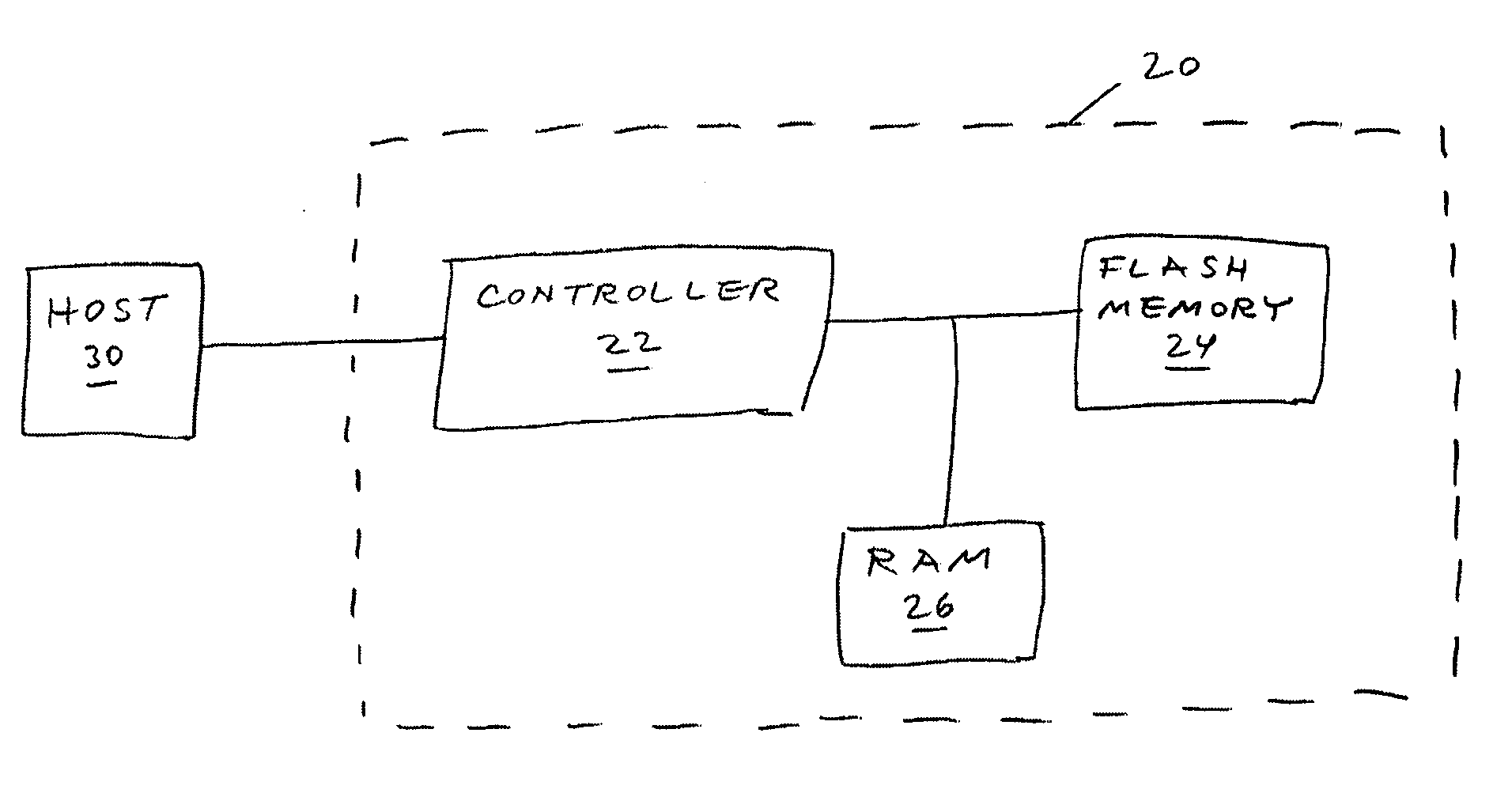
[0046]The principles and operation of a flash memory decoder according to the present invention may be better understood with reference to the drawings and the accompanying description.

[0047]The present invention uses iterative decoders in the ECC employed in flash memory storage systems that use MBC flash memory devices. The method of the present invention operates as follows:[0048]a. User data are provided by an external host computer to a flash memory storage system of the present invention in order to be stored for later recall.[0049]b. The encoder part of an ECC module of the storage system encodes the user data into a codeword that is a representation of the user data plus some extra information that allows overcoming errors in the data should such errors occur. Typically the stored codeword includes the original user data bits plus some parity bits that are computed based on the user data bits. The encoding may be done using any ECC algorithm known in the art, as long as ther...


PUM


Abstract

Data are encoded as a systematic or nonsystematic codeword that is stored in a memory such as a flash memory. A representation of the codeword is read from the memory. A plurality of bits related to the representation of the codeword is decoded iteratively. The plurality of bits could be, for example, part or all of the representation of the codeword itself or part or all of the results of preliminary processing of part or all of the representation of the codeword.

Description

[0001]This patent application claims the benefit of U.S. Provisional Patent Application No. 60 / 806,534, filed Jul. 4, 2006FIELD AND BACKGROUND OF THE INVENTION[0002]The present invention relates to error correction of digital data and, more particularly, to a method of error correction for flash memory devices that store multiple bits per cell.[0003]Flash memory devices have been known for many years. Typically, each cell within a flash memory stores one bit of information. Traditionally, the way to store a bit has been by supporting two states of the cell—one state represents a logical “0” and the other state represents a logical “1”. In a flash memory cell the two states are implemented by having a floating gate above the cell's channel (the area connecting the source and drain elements of the cell's transistor), and having two valid states for the amount of charge stored within this floating gate. Typically, one state is with zero charge in the floating gate and is the initial un...

Claims


Application Information

Patent Timeline
Patent Type & Authority Applications(United States)
IPC IPC(8): G11C29/00
CPCG06F11/1072G11C29/00G11C11/5642G11C16/34
Inventor ALROD, IDANSHARON, ERANLITSYN, SIMON
Owner RAMOT AT TEL AVIV UNIV LTD
Why Eureka
Try Eureka