Method For Clamping And Turning A Vehicle Wheel Shape

Inactive Publication Date: 2008-01-17
SMYTH LARRY C
View PDF12 Cites 7 Cited by
  • Summary
  • Abstract
  • Description
  • Claims
  • Application Information

AI Technical Summary

Benefits of technology

[0015] It is another object of the invention to provide a method for forming a ve

Problems solved by technology

As modern vehicles use larger wheels than prior generations, and as consumers insist on quieter and smoother running vehicles, it has become more and more of a challenge to achieve the increasingly tighter design specifications with conventional first operation—second operation turning.
While the above technique is attractive, it does require a more complex and expensive casting or forging to provide the necessary additional stepped ring or extension for clampi

Method used


Image

  • Method For Clamping And Turning A Vehicle Wheel Shape
  • Method For Clamping And Turning A Vehicle Wheel Shape
  • Method For Clamping And Turning A Vehicle Wheel Shape

Examples


Embodiment Construction

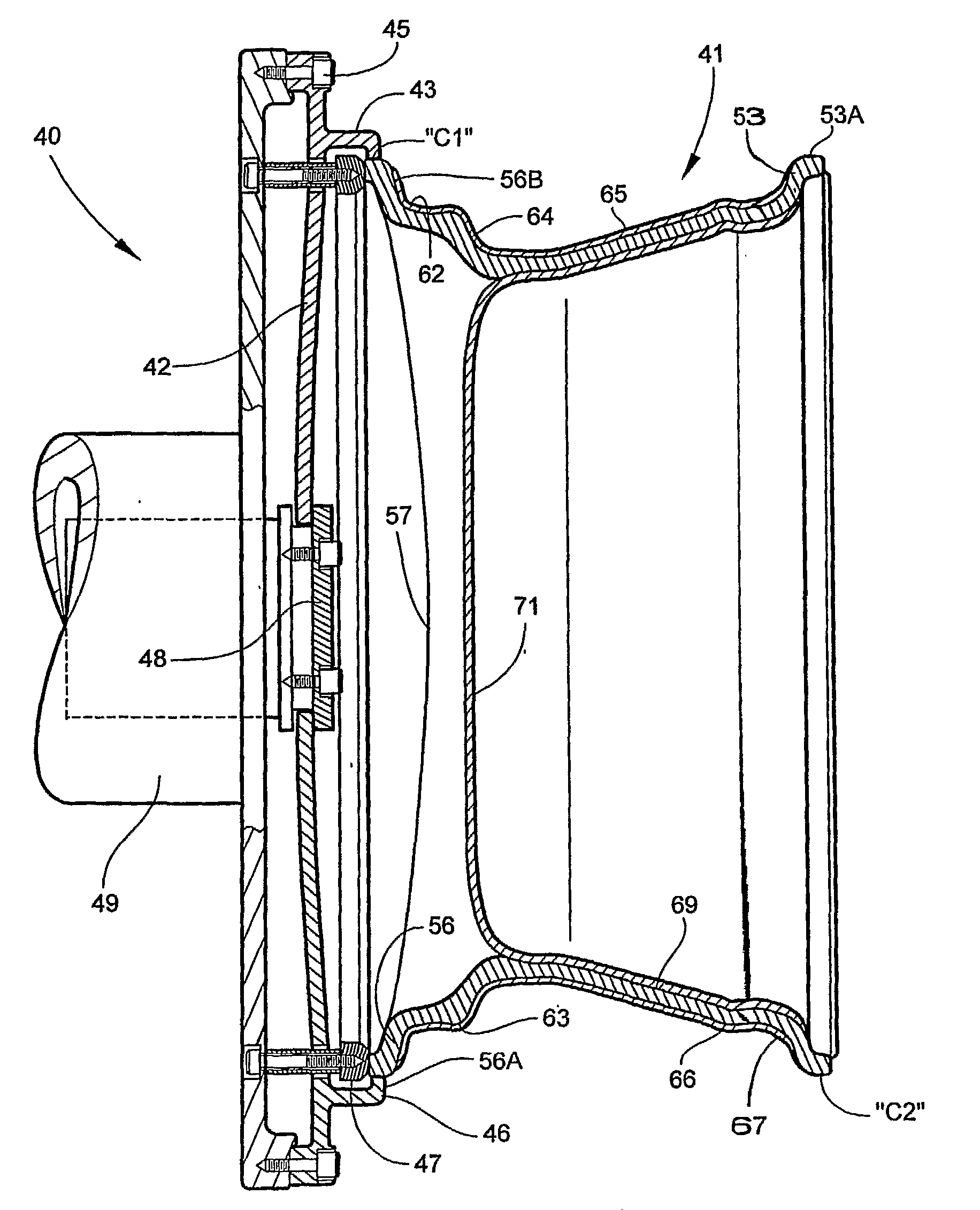
[0042] Referring now specifically to the drawings, FIG. 3 shows a chuck 40 of a lathe applicable for machining (or “turning”) a cast or forged alloy wheel shape 41 to form a vehicle wheel according to a preferred embodiment of the present invention. The chuck 40 comprises a flexible, radially-segmented diaphragm 42 including an annular clamping flange 43 designed to engage the wheel shape 41 along a small axial clamping area “C1”. This clamping area is preferably less than 10 mm. In a most preferred embodiment, the clamping area is in the range of 4-6 mm. The clamping flange 43 extends along substantially an entire circumference of the wheel shape 41—preferably, along 80-100% of the circumference.

[0043] The diaphragm 42 is fixedly secured to the chuck 40 at an outer peripheral edge by bolts 45 or other suitable fasteners. The clamping flange 43 is integrally formed with a body of the diaphragm 42, and has an annular inwardly-turned lip 46 adapted for engaging the wheel shape 41. Th...


PUM

PropertyMeasurementUnit
Lengthaaaaaaaaaa
Shapeaaaaaaaaaa
Areaaaaaaaaaaa

Abstract

A method for forming a vehicle wheel including a wheel rim defining opposing inboard and outboard annular flanges, inboard and outboard tire bead seats adjacent respective inboard and outboard flanges, and a rim barrel between the inboard and outboard tire bead seats. The method includes the step of machining a wheel shape in a clamping area adjacent one of the inboard and outboard flanges of the vehicle wheel. The clamping area of the wheel shape is then secured within a chuck of a lathe. In one chucking, the wheel shape is machined to form the inboard and outboard tire bead seats of the vehicle wheel.

Description

TECHNICAL FIELD AND BACKGROUND OF THE INVENTION [0001] This invention relates broadly to the manufacture of vehicle wheels, and more specifically, to an improved method for clamping and turning a wheel shape or other cup-shaped part. [0002] Steel wheels are almost always made of two-pieces, a center or spider, and the rim. They are also almost always made from sheet material. Aluminum wheels can be made in the same manner, but most light alloy wheels are made from either cast or forged wheel shapes. The initial styling is created by the casting mold or forging dies as are the functional wheel surfaces. These latter surfaces are formed with excess material, which is then removed in subsequent precision machining operations. Most of the initial shape is turned on lathes, and then drilling of the lug and valve holes is done on milling or drilling machines. [0003] Machining requires proper part holding. For milling and drilling, the part needs to be positioned correctly and rigidly clam...

Claims


Application Information

Patent Timeline
IPC IPC(8): B23B5/34B23B5/00B23B31/18B23B31/32
CPCB23B5/00B23B31/18B23B31/32Y10T82/10B23B2231/12B23B2260/134B23B2270/54B23B2215/08
Inventor SMYTH, LARRY C.
Owner SMYTH LARRY C
Why Eureka
Try Eureka