Engine cylinder head cover with integral breather apparatus, and engine incorporating same

a breather apparatus and engine technology, applied in the direction of combustion engines, combustion air/fuel air treatment, charge feed systems, etc., can solve the problems of poor space behind the rib to be left as an unused dead space, and the breather chamber as a whole is not used as effectively, so as to promote gas-liquid separation and improve the fluidity of molten metal

Inactive Publication Date: 2008-01-17
HONDA MOTOR CO LTD
View PDF6 Cites 11 Cited by
  • Summary
  • Abstract
  • Description
  • Claims
  • Application Information

AI Technical Summary

Benefits of technology

[0011]The present invention has been made in view of the above situation, and it is an object of the present invention to provide a breather apparatus for an internal combustion engine which, when casting a cylinder head cover, can improve the fluidity of molten metal and promote gas-liquid separation through effective use of an entire breather chamber.
[0017]In the breather apparatus for an internal combustion engine according to the first aspect of the present invention, all the ribs extend from one side wall included in the peripheral wall, each of the ribs extending up to where it is continuous with one of the fixing bosses. This improves the fluidity of molten metal when casting the cylinder head cover during manufacture thereof. Pouring molten metal through a casting gate such that the molten metal flows toward the one side wall can further improve the fluidity of the molten metal, easily allowing the molten metal to fill the mold portions corresponding to the fixing bosses in a consistent and reproducible way.
[0018]Each of the ribs extends obliquely relative to a direction in which the blowby gas flows in through one of the inflow ports with a projecting lower edge portion of the rib partly cut out forming a concave portion. This causes most of the blowby gas flowing in through the inflow port to be guided by the obliquely extending rib to follow a long maze-like flow path, whereas some of the blowby gas is allowed to advance through the concave portion formed in the rib to a space on the back side of the rib (on the side opposite to the inflow port). In this way, the entire breather chamber can be effectively used, causing no dead space to be generated, to promote gas-liquid separation.
[0020]Thus, with the blowby gas introduced into the breather chamber through the two inflow ports, gas-liquid separation can be efficiently carried out making use of the entire breather chamber without generating any unused dead space.

Problems solved by technology

This results in a poor fluidity of the molten metal during manufacture of the cylinder head cover.
This causes a space behind the rib to be left as an unused dead space.
Thus, the breather chamber as a whole is not used as effectively as it could be.

Method used


Image

  • Engine cylinder head cover with integral breather apparatus, and engine incorporating same
  • Engine cylinder head cover with integral breather apparatus, and engine incorporating same
  • Engine cylinder head cover with integral breather apparatus, and engine incorporating same

Examples


Embodiment Construction

[0031]A selected illustrative embodiment of the present invention will now be described, with reference to the drawing FIGS. 1 to 6. In the present specification, the relative directional terms front, rear, left, right, upper and lower are described from the vantage point of a user of a motorcycle on which an internal combustion engine is transversely mounted, where the user is seated on the vehicle and facing forward.

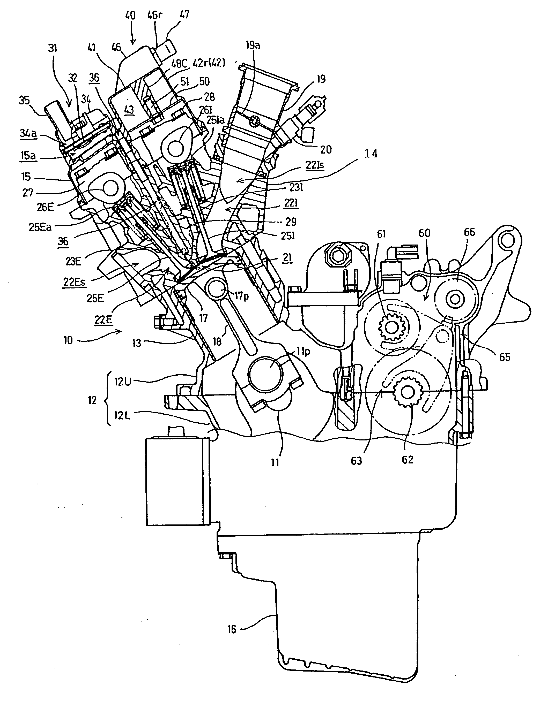
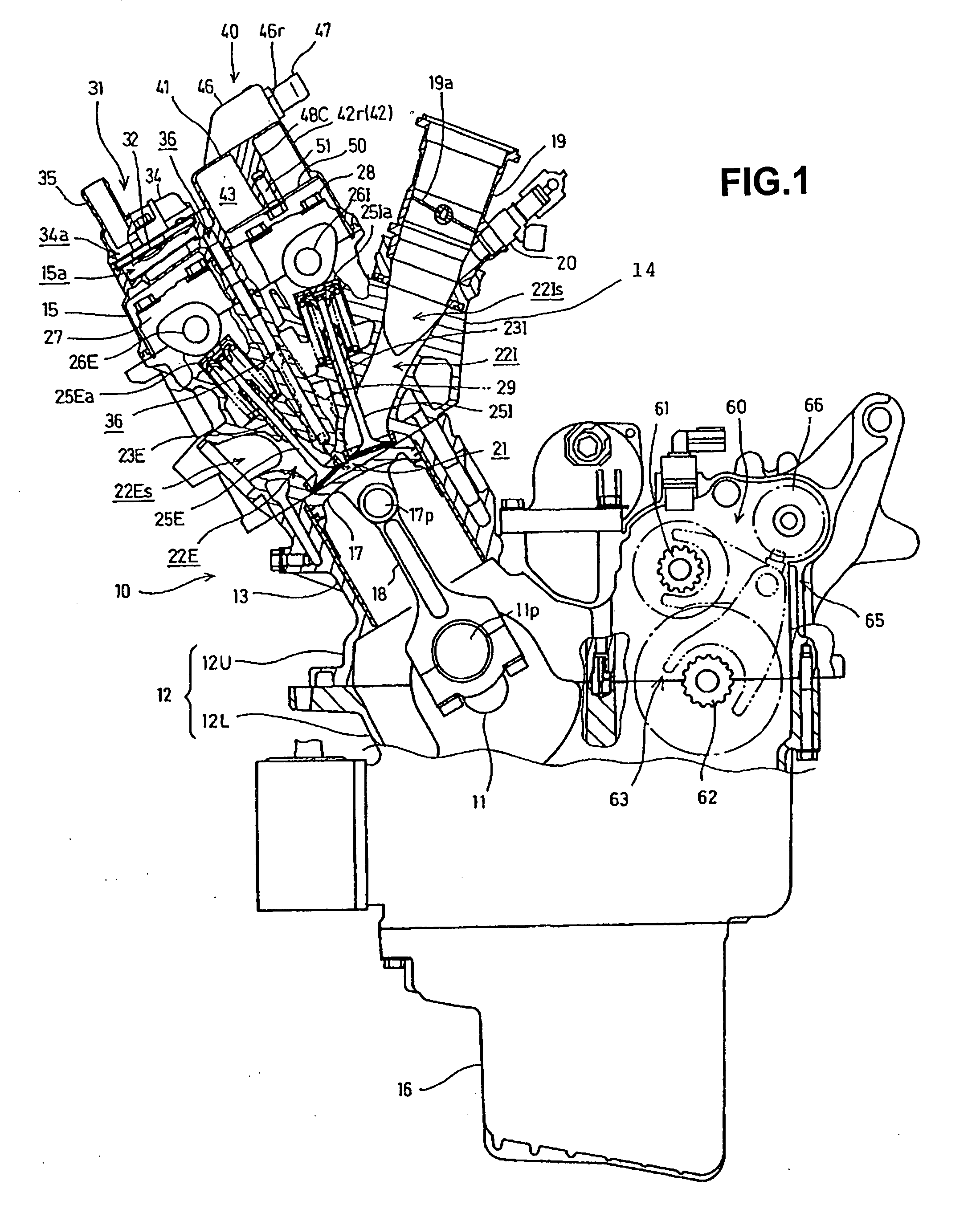
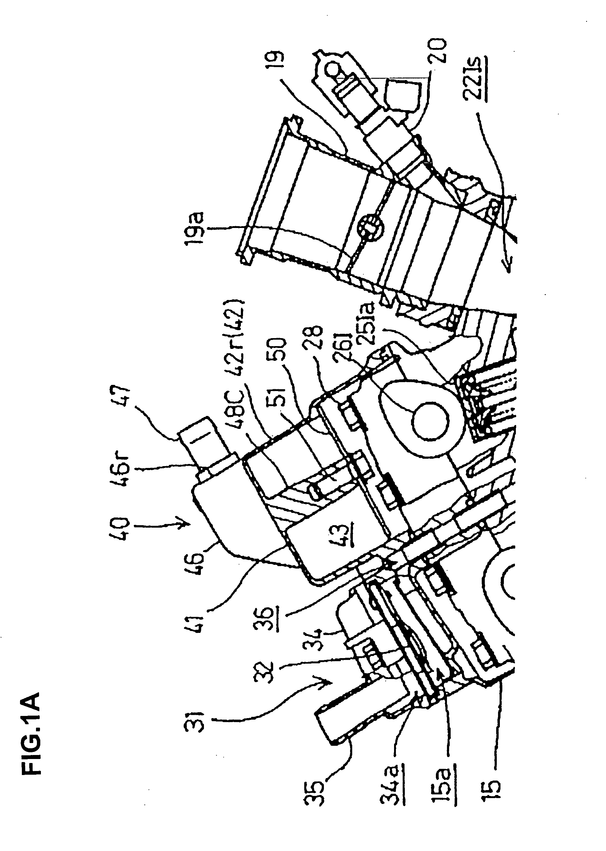
[0032]An internal combustion engine 10 according to the illustrative embodiment is a water-cooled, double overhead cam (DOHC), four-cylinder, four-stroke engine. It is adapted to be mounted transversely on a motorcycle frame (not shown), with a crankshaft 11 thereof oriented transverse to a longitudinal axis of the motorcycle frame.

[0033]FIG. 1 is a cross-sectional view of the internal combustion engine 10. Referring to FIG. 1, the engine 10 includes a crankcase 12 having an upper part 12U and a lower part 12L. A cylinder block 13 is projectingly formed on the upper cr...


PUM


Abstract

A breather apparatus for an internal combustion engine which, when casting a cylinder head cover, can improve the fluidity of molten metal and promote gas-liquid separation through effective use of an entire breather chamber. A breather apparatus for an internal combustion engine has a cylinder head cover in which a breather chamber is formed. In the breather chamber, a number of ribs extend from a side wall included in a peripheral wall of the chamber obliquely relative to a direction in which blowby gas flows in through inflow ports. The ribs extend up to where they are continuous with respective fixing bosses. The ribs include projecting lower edge portions which are partly cut out, forming respective concave portions.

Description

CROSS-REFERENCE TO RELATED APPLICATIONS[0001]The present invention claims priority under 35 USC 119 based on Japanese patent application No. 2006-192429, filed on Jul. 13, 2006, the subject matter of which is incorporated by reference herein.BACKGROUND OF THE INVENTION[0002]1. Technical Field of the Invention[0003]The present invention relates to a cylinder head cover including an integrally formed breather apparatus, and to an engine incorporating the cylinder head cover.[0004]2. Background Art[0005]Various cylinder head covers have been proposed in which a breather chamber is formed by a peripheral wall projecting inside of the cylinder head cover, and a breather plate covering an opening of the peripheral wall, where plural ribs are formed extending from the peripheral wall in the breather chamber, thereby setting long maze-like blowby gas flow paths so as to promote gas-liquid separation (see published patent document JP-A 2005-307852, for example).[0006]In the cylinder head cov...

Claims


Application Information

Patent Timeline
Patent Type & Authority Applications(United States)
IPC IPC(8): F02B25/06
CPCF02F7/006F02M35/104F02M35/10222
Inventor TAWARADA, YUICHIYAMASAKI, TAKUYAFURUYA, MASASHI
Owner HONDA MOTOR CO LTD
Why Eureka
Try Eureka