
Hydraulic valve actuated by piezoelectric effect

a piezoelectric effect and valve actuator technology, applied in the direction of valve operating means/releasing devices, mechanical equipment, transportation and packaging, etc., can solve the problems of dimensional changes in the piezoelectric stack, shift in the regulated pressure, and heating in both the coil and the driver circui

Inactive Publication Date: 2008-01-17
FORD GLOBAL TECH LLC
View PDF21 Cites 8 Cited by
  • Summary
  • Abstract
  • Description
  • Claims
  • Application Information

AI Technical Summary

Benefits of technology

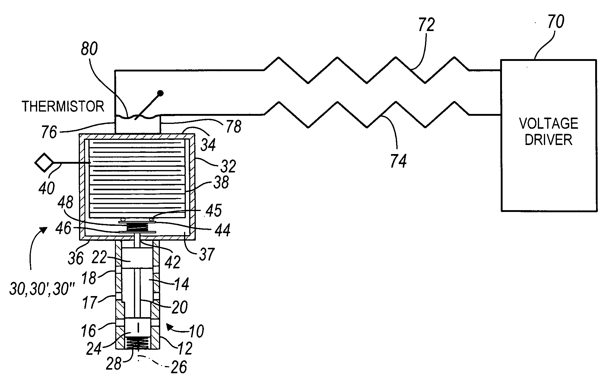
[0005]A valve-actuator for a hydraulic valve includes a valve chamber, ports spaced mutually and opening into the chamber, a spool axially located in the chamber for opening and closing hydraulic connections between at least two of the ports as the spool moves axially in the chamber. An actuator includes a housing having mutually spaced surfaces, and a piezoelectric element or stack located in the housing between the surfaces. The stack expands and contracts in response to an electric signal applied to the element. The spool moves axially in the chamber in response to expansion and contraction of the stack. The stack of piezoelectric elements expands when a voltage is applied and contracts when voltage is removed. A coupling spring, interposed between the stack and the valve spool, allows extra freedom of motion in case the stack's spring rate is excessive.
[0007]Temperature variations cause dimensional changes in the piezoelectric stack. These dimensional changes cause a shift in the regulated pressure. A thermistor located in the force motor assembly, in conjunction with the feedback resistors, allows the voltage across the stack to be controlled with temperature, and it helps null the effect of expansion of the piezoelectric stack. The parallel resistor path lowers the input impedance of the system and decreases its susceptibility to electromagnetic interference.
[0008]Conventional designs use an electromagnetic solenoid to provide force needed to move either the spool or a pilot section poppet valve. These electromagnetic solenoids require continuous current of up to 1 Amp to hold a pressure. This energy causes heating in both the coil and driver circuit. The piezoelectric force motor draws current only to change the position of the spool in the chamber. Thereafter, it resembles a reverse biased diode with the high resistance thermistor in parallel. This arrangement reduces the energy consumption and lessens the need for heat dissipation in the driver. The piezoelectric regulator valve with damping resistors has smaller pressure oscillations than a conventional system, which relies on hydraulic damping.

Problems solved by technology

Temperature variations cause dimensional changes in the piezoelectric stack.
These dimensional changes cause a shift in the regulated pressure.
This energy causes heating in both the coil and driver circuit.

Method used


Image

  • Hydraulic valve actuated by piezoelectric effect
  • Hydraulic valve actuated by piezoelectric effect
  • Hydraulic valve actuated by piezoelectric effect

Examples


Embodiment Construction

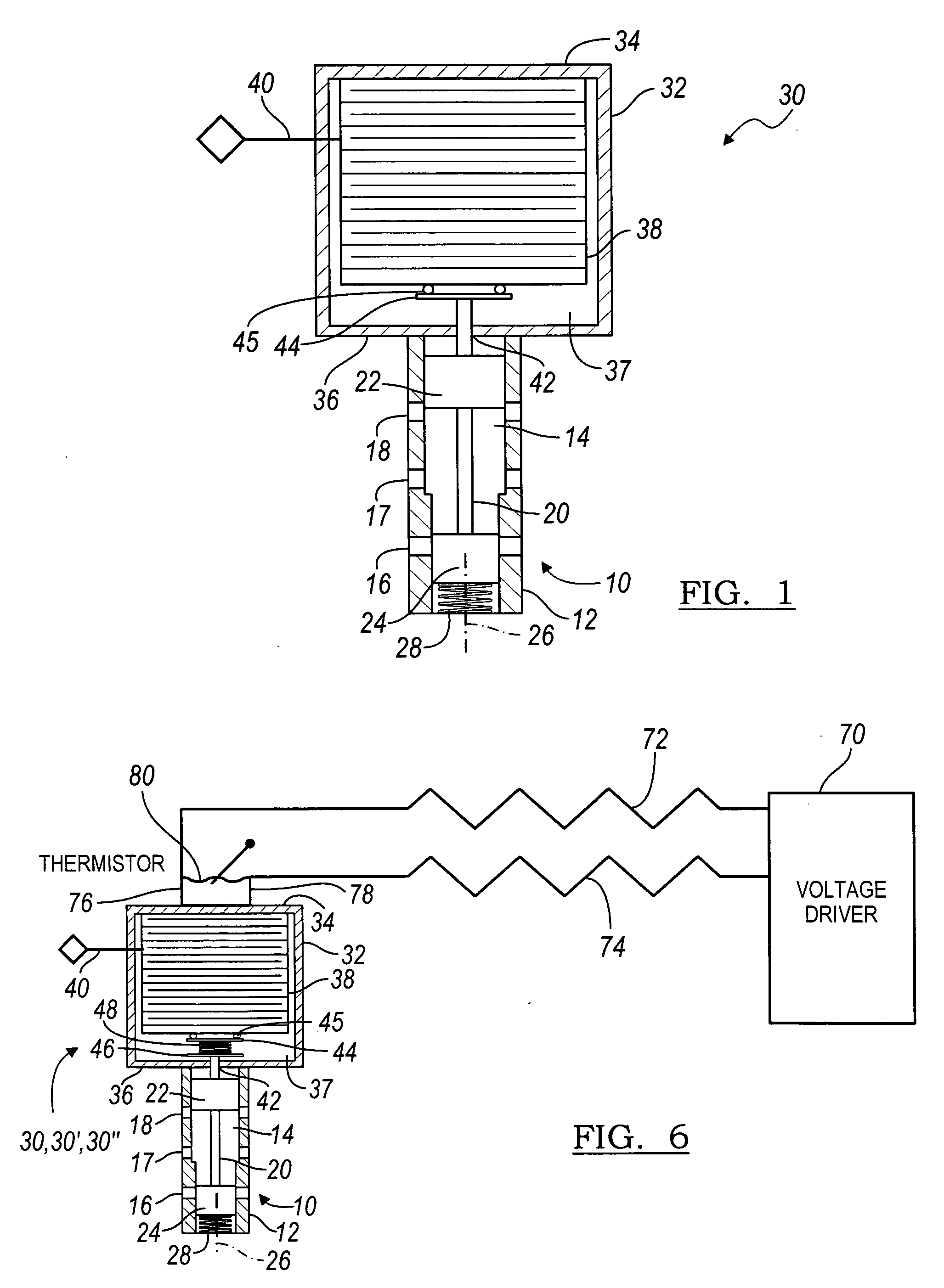
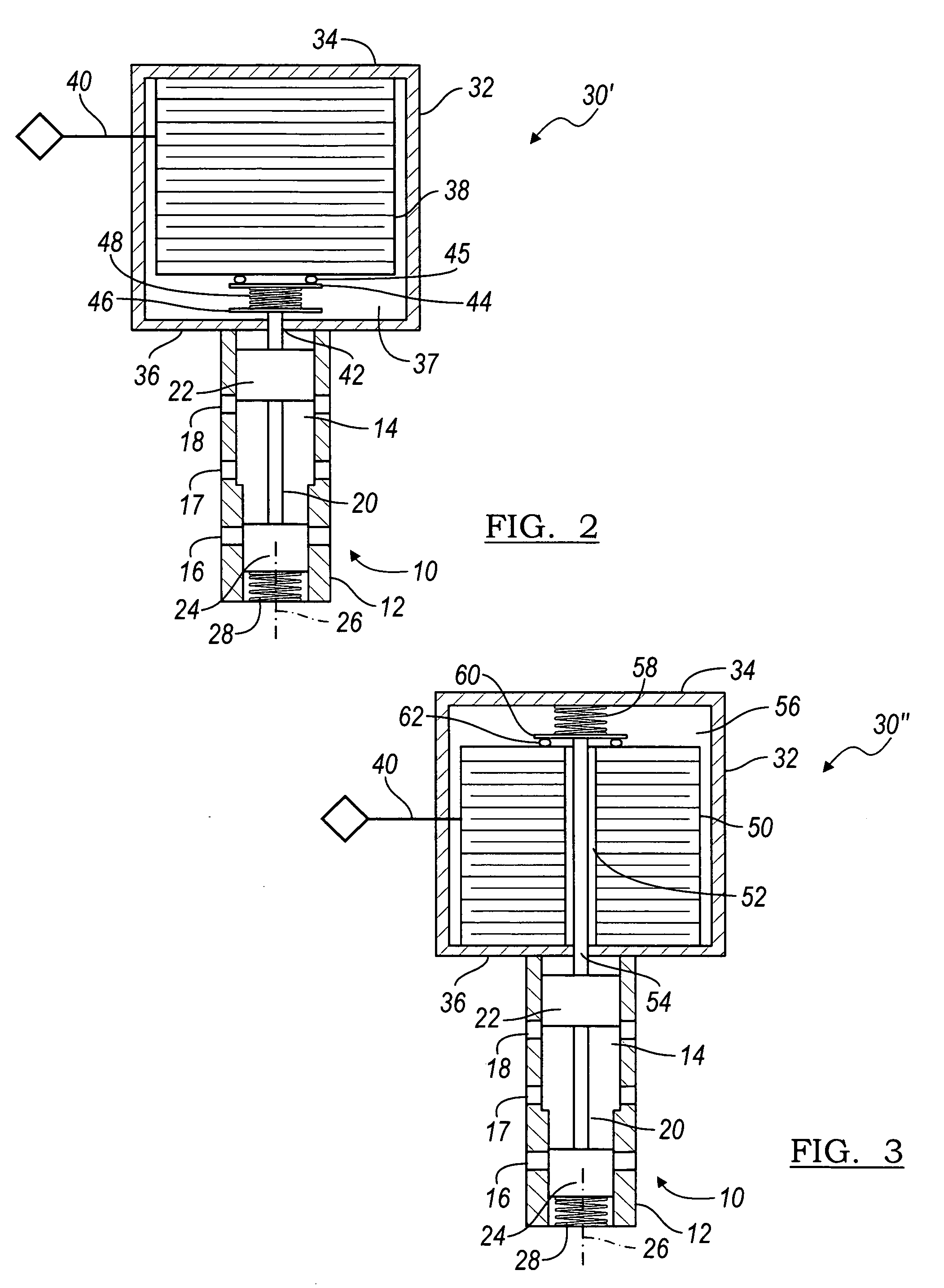
[0017]Referring to FIG. 1, a regulator valve 10 includes a valve body 12; a cylindrical chamber 14 formed in the body; and ports 16, 17, 18 spaced mutually along the wall of the body and opening into the chamber. A valve spool 20, located in the chamber 14, is formed with axially spaced control lands 22, 24, which open and close the ports and hydraulic connections among the ports as the spool moves along the axis 26 of the chamber. At least one port is an inlet port, through which supply flow enters chamber 14. At least one other port is an outlet port 18, through which flow is exhausted to lower the pressure in chamber 14. At least one other port is a control port 17, through which pressure at a regulated magnitude exits the valve through chamber 14, depending, at least in part, on the degree to which the inlet and outlet ports are fully or partially opened by a control land 22, 24.

[0018]A compression spring 28, located in chamber 14, applies a spring force to the spool 20 at land ...


PUM


Abstract

A valve-actuator for a hydraulic valve includes a valve chamber, ports spaced mutually and opening into the chamber, a spool axially located in the chamber for opening and closing hydraulic connections between at least two of the ports as the spool moves axially in the chamber. An actuator includes a housing having mutually spaced surfaces, and a piezoelectric element located in the housing between the surfaces, the element expanding and contracting in response to an electric signal applied to the element. A temperature compensation and motion damping circuit comprising feedback resistors and a thermistor. The spool moves axially in the chamber in response to expansion and contraction of the element.

Description

BACKGROUND OF THE INVENTION[0001]The preferred embodiment relates generally to an apparatus for actuating a hydraulic valve spool that moves in a chamber to control a hydraulic function produced by the valve. More particularly, it pertains to regulating the magnitude of fluid pressure at an outlet port of the valve using piezoelectric actuation of the valve spool and stabilizing the valve with an electrical feedback circuit.[0002]Hydraulic valves include a chamber, a spool formed with control lands, which open and closed inlet and outlet ports that communicate mutually through the chamber as the spool moves. Various techniques are used to develop forces that are applied to the spool to determine its position in the chamber including forces produced by springs, hydraulic pressure on the lands, and forces produced by an electromechanical actuator acting on the spool.[0003]In the hydraulic systems of automatic transmissions for motor vehicles, pressure regulating valves typically use m...

Claims


Application Information

Patent Timeline
Patent Type & Authority Applications(United States)
IPC IPC(8): F15B13/044
CPCF16K31/025Y10T137/86622F16K31/008F16K11/07
Inventor BURKHART, ROBERT O.PIETRON, GREGORY M.FUJII, YUJI
Owner FORD GLOBAL TECH LLC
Learn More