
Method for bonding and debonding a workpiece to a manufacturing fixture

a manufacturing fixture and workpiece technology, applied in the field of work holders, can solve the problems of extremely cost-effective bonding and debonding operations, only taking a few seconds each, etc., and achieve the effect of reducing lead time and cost and improving part quality

Inactive Publication Date: 2008-01-17
PENN STATE RES FOUND
View PDF28 Cites 12 Cited by
  • Summary
  • Abstract
  • Description
  • Claims
  • Application Information

AI Technical Summary

Benefits of technology

The present invention is a system and method for securely loading and unloading workpieces from a manufacturing fixture using a radiation responsive adhesive as the bonding agent. The adhesive is applied to a gripper pin on the fixture and the workpiece is pushed against the gripper pins, causing the adhesive to solidify and bond the workpiece to the fixture. The process is fast and cost-effective, and the bond can be easily deboned by transmitting radiant energy through the gripper pins. The technical effect of this invention is to provide a reliable and efficient method for securely holding and manipulating workpieces during manufacturing processes.

Problems solved by technology

The bond and debond operations only take a few seconds each and are extremely cost effective.

Method used


Image

  • Method for bonding and debonding a workpiece to a manufacturing fixture
  • Method for bonding and debonding a workpiece to a manufacturing fixture
  • Method for bonding and debonding a workpiece to a manufacturing fixture

Examples


Embodiment Construction

[0062] The disclosure invention can be configured for any manufacturing operation requiring the holding of a workpiece. The embodiments contained herein are directed to high volume machining for illustration purposes, but are not limited to such manufacturing applications.

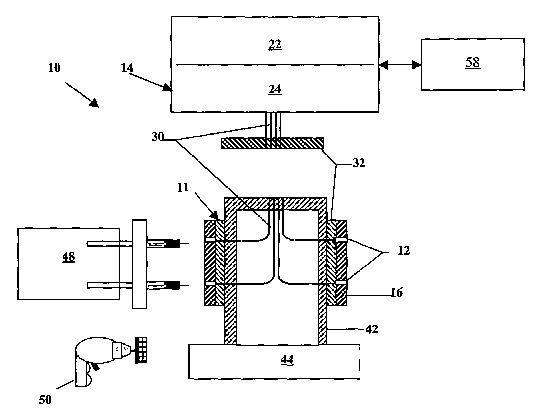
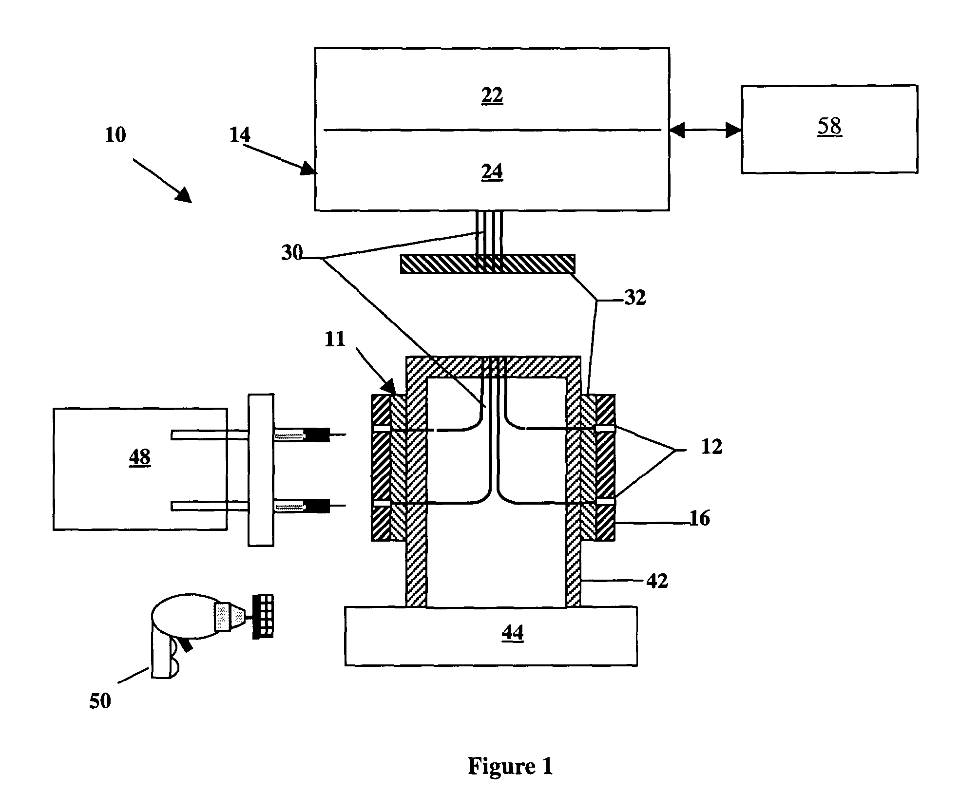
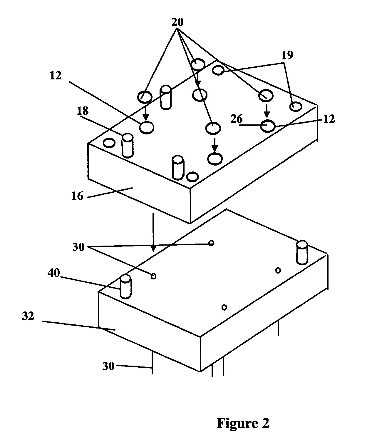
[0063] The present invention 10 illustrated in FIGS. 1 and 2 include gripper pins 12, radiant energy transmission system 14, gripper pin chassis 16, and removable / retractable locator pins 18 and locator pads 19. Also shown are radiant energy source 22, optical routing system 24, light guides 30 and light guide chassis 32, which are components of radiant energy transmission system 14. A computer control system 58 controls the emission of radiant energy from the radiant energy transmission system 14 to the gripper pins 12. Radiation responsive adhesive 20 is applied to a contract surface 26 of the gripper pins 12 for bonding the workpiece 28 to the gripper pins 12. Gripper pin chassis 16 and light guide chassis 32 a...


PUM

PropertyMeasurementUnit
pressureaaaaaaaaaa
melting pointsaaaaaaaaaa

Abstract

A system and a method by which workpieces are bonded to and debond from a manufacturing fixture using a radiation responsive adhesive as a bonding agent. The system includes curing the adhesive agent during loading within seconds, and structurally weakens the adhesive bond during unloading within seconds. During the workpiece loading cycle, an adhesive dispenser deposits radiation responsive adhesive on to a load bearing, light transmittive surface, known as gripper pins. The workpiece is subsequently pushed against the locators, and towards the gripper pins causing the adhesive to interpose between workpiece and gripper pins, curing radiant energy is transmitted through the gripper pins and on to the adhesive to cure adhesive and bond the workpiece to the fixture. Therefore, the bond is structurally weakened or debonded in order to remove the workpiece from the fixture after manufacturing.

Description

CROSS REFERENCE TO RELATED APPLICATIONS [0001] This application claims the benefit of Provisional Application No. 60 / 402,145, entitled LIGHT ACTIVATED ADHESIVE GRIPPER (LAAG) TECHNOLOGY AND PROCESS filed on Aug. 7, 2002, and which is incorporated herein by reference.STATEMENT REGARDING FEDERALLY SPONSORED RESEARCH OR DEVELOPMENT [0002] This invention was made partially with U.S. Government support from the National Science Foundation under Contract Number DMII01-25515. The U.S. Government has certain rights in the invention.BACKGROUND OF THE INVENTION [0003] The present invention relates to work holders, and particularly relates to such devices using radiant energy to bond and debond a radiation responsive adhesive interposed between a workpiece and a fixture. [0004] Fixtures are used in manufacturing practice to locate and hold the workpiece relative to the manufacturing process, assembly process, or inspection process. One of the most demanding manufacturing operations is machinin...

Claims


Application Information

Patent Timeline
Patent Type & Authority Applications(United States)
IPC IPC(8): B32B37/12G03C1/74B23Q3/08B29C65/14B29C65/76C09J5/00
CPCB23Q3/084B29C65/4865B29C65/1406B29C65/1409B29C65/1416B29C65/1464B29C65/1487B29C65/1606B29C65/1616B29C65/1687B29C65/4845B29C65/76C09J5/00B29C65/1435B29C65/1483B29C66/472B29C66/5326B29C65/1635B29C65/1664B29C65/1683B29C65/4835B29C65/485B29C65/1403B27G11/02B29C66/1122
Inventor DEMETER, EDWARD C.
Owner PENN STATE RES FOUND
Learn More