Low-voltage detection reset circuit

a low-voltage detection and reset circuit technology, applied in electronic switching, pulse automatic control, pulse technique, etc., can solve the problem of large circuit siz

Active Publication Date: 2008-01-17
SEMICON COMPONENTS IND LLC
View PDF1 Cites 9 Cited by
  • Summary
  • Abstract
  • Description
  • Claims
  • Application Information

AI Technical Summary

Benefits of technology

[0013] This invention is directed to solve the problems addressed above, and offers a low-voltage detection reset circuit including a power-on reset circuit that outputs a first reset pulse in response to a rise of a power supply voltage, a detection level setting circuit capable of variably setting a detection level corresponding to the power supply voltage, a low-voltage detection circuit that compares the detection level with a reference voltage that is independent of the power supply voltage and outputs a second reset pulse when the detection level is equal to or lower than the reference level and a control circuit that controls the detection level setting circuit so that the detection level is set to a default value in response to the first reset pulse.

Problems solved by technology

However, since the low-voltage detection reset circuit described above includes the low-voltage detection circuit with the power-on reset function 20, it has problems that the electric current I0 flows in a stand-by mode and a size of the circuit is large.

Method used


Image

  • Low-voltage detection reset circuit
  • Low-voltage detection reset circuit
  • Low-voltage detection reset circuit

Examples


Embodiment Construction

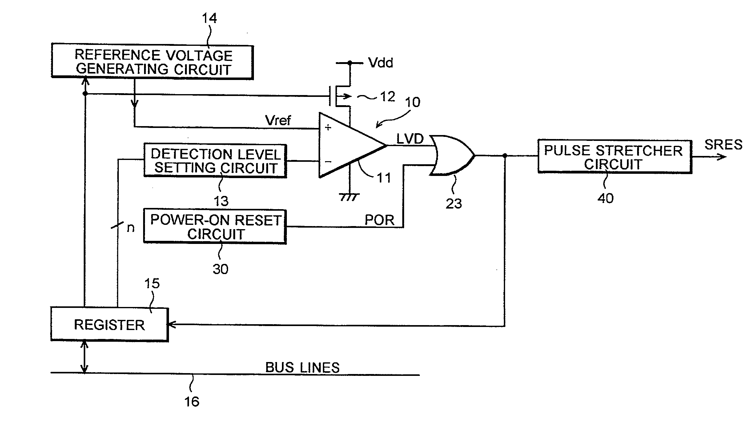
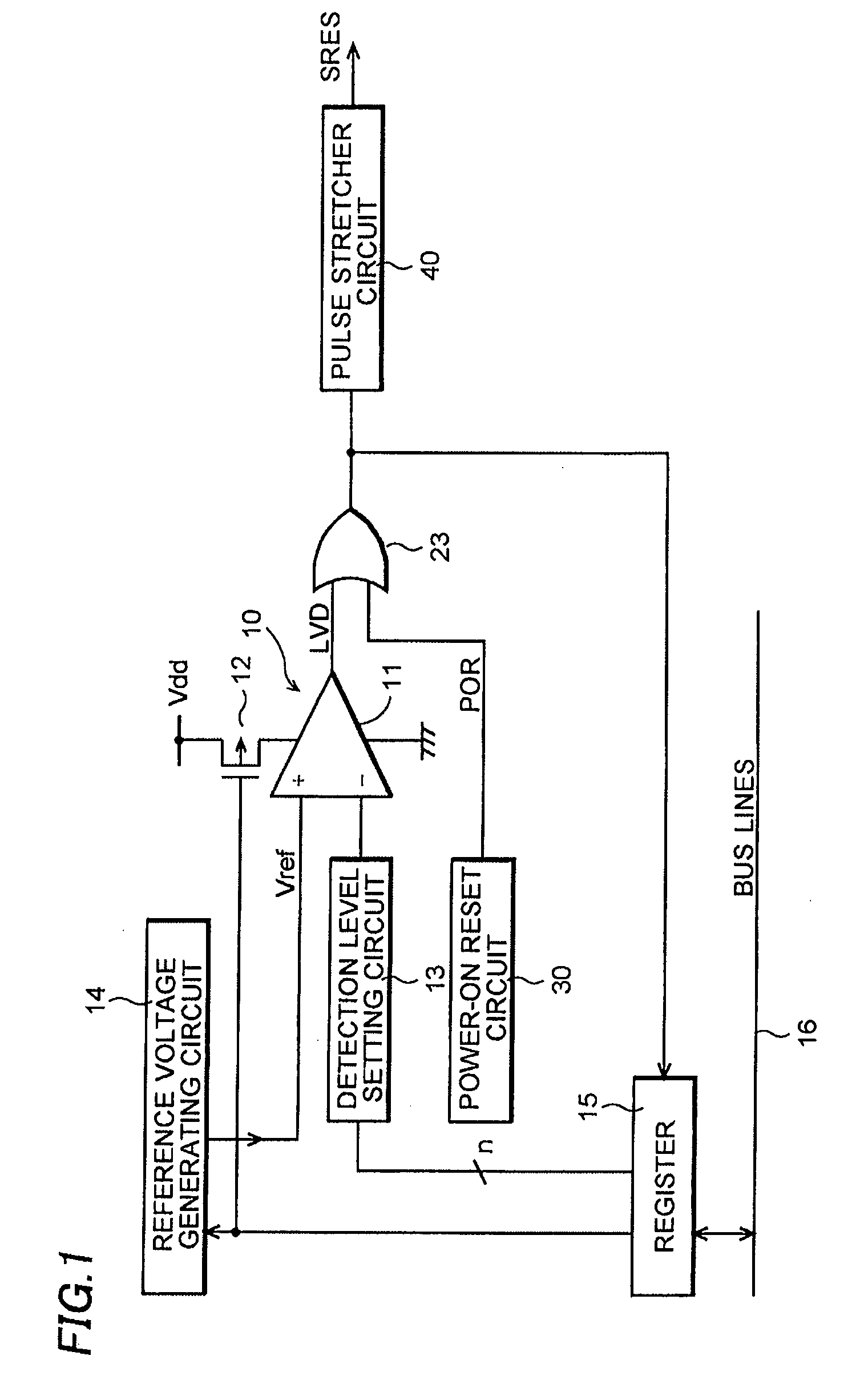
[0018] A low-voltage detection reset circuit according to an embodiment of this invention is described referring to the drawings. FIG. 1 is a circuit diagram of the low-voltage detection reset circuit. The same components in FIG. 1 as in FIG. 4 are denoted by the same symbols. The low-voltage detection reset circuit according to the embodiment of this invention is provided with a power-on reset circuit 30 that operates only at power-on and outputs a reset pulse of a high level and is configured to set a detection level of a detection level setting circuit 13 at a default value using the reset pulse and to activate a programmable low-voltage detection circuit 10. An output of the power-on reset circuit 30, as well as an output of the programmable low-voltage detection circuit 10, is inputted to an OR circuit 23, from which a system reset signal SRES is obtained. After the programmable low-voltage detection circuit 10 is activated, the detection level of the programmable low-voltage d...


PUM


Abstract

A low-voltage detection reset circuit that suppresses a current consumption in a stand-by mode and is reduced in a size is offered. The low-voltage detection reset circuit is provided with a power-on reset circuit that operates only at power-on and outputs a reset pulse and is configured to set a detection level of a detection level setting circuit at a default value using the reset pulse and to activate a programmable low-voltage detection circuit. After the programmable low-voltage detection circuit is activated, a detection level of the programmable low-voltage detection circuit can be modified from the default value by a register.

Description

CROSS-REFERENCE OF THE INVENTION [0001] This application claims priority from Japanese Patent Application No. 2006-169832, the content of which is incorporated herein by reference in its entirety. BACKGROUND OF THE INVENTION [0002] 1. Field of the Invention [0003] This invention relates to a low-voltage detection reset circuit that detects reduction in a power supply voltage supplied to a semiconductor integrated circuit and resets a system of the semiconductor integrated circuit. [0004] 2. Description of the Related Art [0005] When a programmable low-voltage detection circuit is incorporated into a microcomputer, a low-voltage detection circuit with a power-on reset function has been also incorporated in the microcomputer in order to make sure that a reset pulse is generated at power-on (turning-on of a power supply). The programmable low-voltage detection circuit is a low-voltage detection circuit capable of programming a detection level corresponding to a power supply voltage. Th...

Claims


Application Information

Patent Timeline
Patent Type & Authority Applications(United States)
IPC IPC(8): H03K3/02H03L7/00
CPCH03K3/356008H03K17/22
Inventor HOTAKA, KAZUO
Owner SEMICON COMPONENTS IND LLC
Why Eureka
Try Eureka