

Method and system for time synchronized trip algorithms for breaker self protection
- Summary
- Abstract
- Description
- Claims
- Application Information
AI Technical Summary
Benefits of technology
Problems solved by technology
Method used
Image

Examples
Embodiment Construction
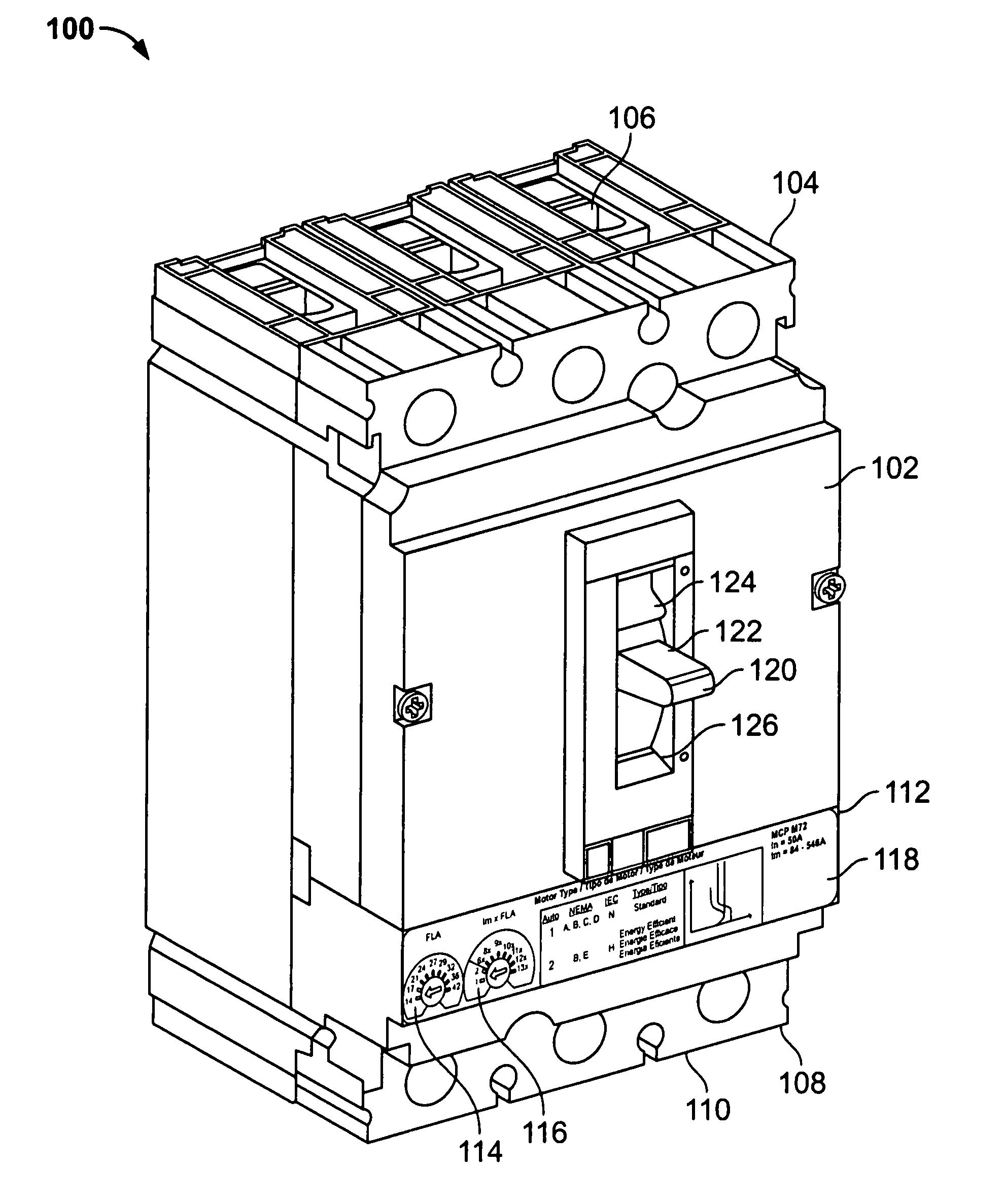
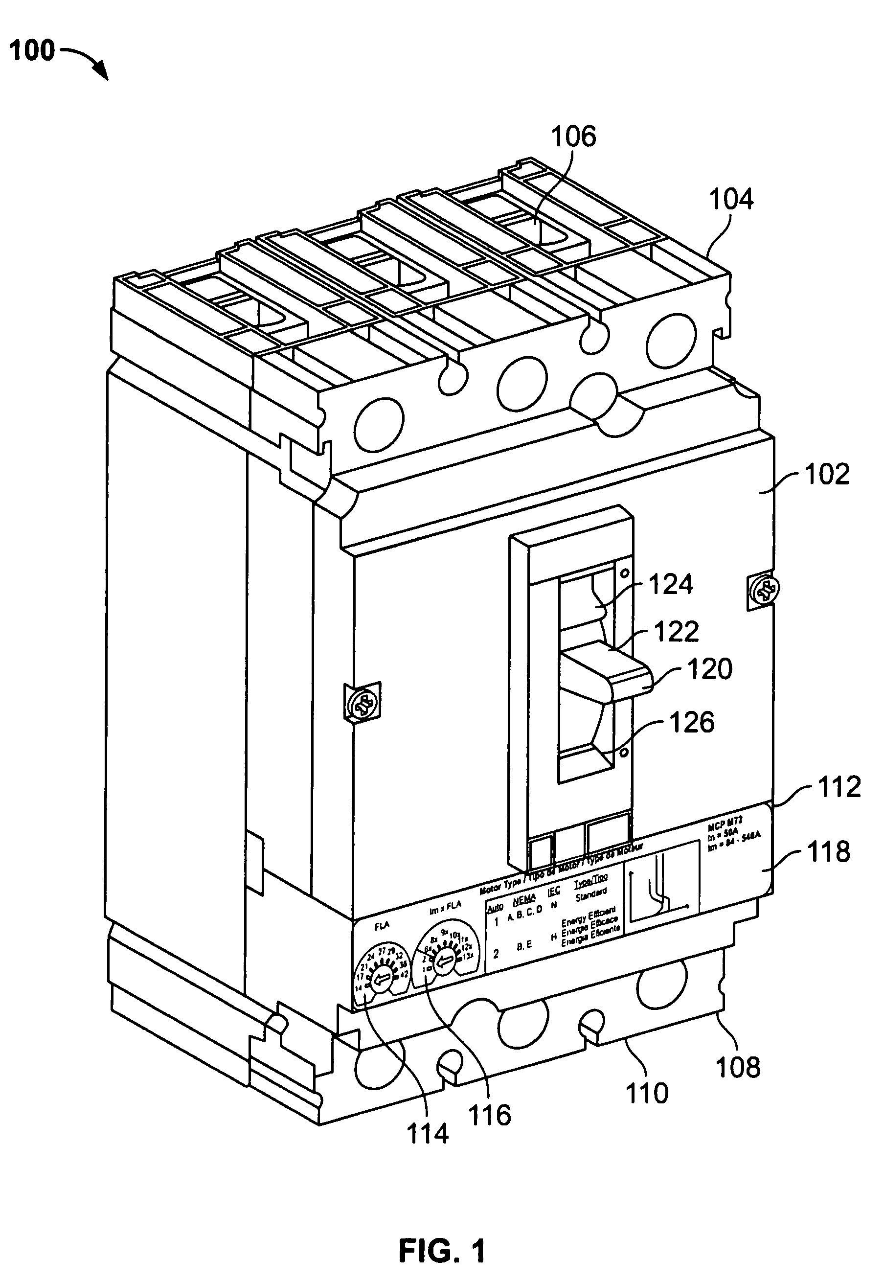
[0024]Turning now to FIG. 1, an electronic motor circuit protector 100 is shown. The motor circuit protector 100 includes a durable housing 102 including a line end 104 having line terminals 106 and a load end 108 having load lugs or terminals 110. The line terminals 106 allow the motor circuit protector 100 to be coupled to a power source and the load terminals 110 allow the motor circuit protector 100 to be coupled to an electrical load such as a motor as part of a motor control center (“MCC”). In this example the motor circuit protector 100 includes a three-phase circuit breaker with three poles, although the concepts described below may be used with circuit protectors with different numbers of poles, including a single pole.
[0025]The motor circuit protector 100 includes a control panel 112 with a full load ampere (“FLA”) dial 114 and an instantaneous trip point (“Im”) dial 116 which allows the user to configure the motor circuit protector 100 for a particular type of motor to be...
PUM
 Abstract
Description
Claims
Application Information