Confocal spectrometer with astigmatic aperturing

a confocal spectrometer and astigmatic technology, applied in the field of molecular spectrometry, can solve the problems of reducing the light to the detector and the greater noise in intensity measurements, affecting the resizability of pinhole apertures, so as to achieve the effect of easy shi

Inactive Publication Date: 2008-01-17
THERMO ELECTRONICS SCI INSTR LLC
View PDF9 Cites 27 Cited by
  • Summary
  • Abstract
  • Description
  • Claims
  • Application Information

AI Technical Summary

Problems solved by technology

The spectrograph input aperture is usually a slit or hole, with a narrower or smaller aperture size resulting in better differentiation between wavelengths, but at the same time leading to decreased light to the detector and greater noise in intensity measurements.
The problem with these arrangements is that for best results, the aperture must be precisely situated at the focus of the beam carrying the sample image.
It is common for arrangements such as rotating / translating masks to eventually fall out of alignment with the focus after extended use, leading to maintenance burdens and / or degraded measurement quality.
Further, while reliable variable-width slits can be constructed using the aforementioned opposing respaceable masks, it is difficult to similarly form a resizable pinhole aperture.
One could conceivably situate one mask pair immediately adjacent another mask pair, with one mask pair allowing slit size variation in one direction and the other mask pair allowing slit size variation in a perpendicular direction so that the two effectively combine to form a variably-sized “pinhole,” but it is difficult to construct a reliable mechanism for doing so without creating an undesirably bulky mask which at least partially obstructs some of the desired light.
In other words, it is difficult to construct such an arrangement without having the masks extend for an undesirable distance in front of and behind the focal point of the image beam.

Method used


Image

  • Confocal spectrometer with astigmatic aperturing
  • Confocal spectrometer with astigmatic aperturing
  • Confocal spectrometer with astigmatic aperturing

Examples


Embodiment Construction

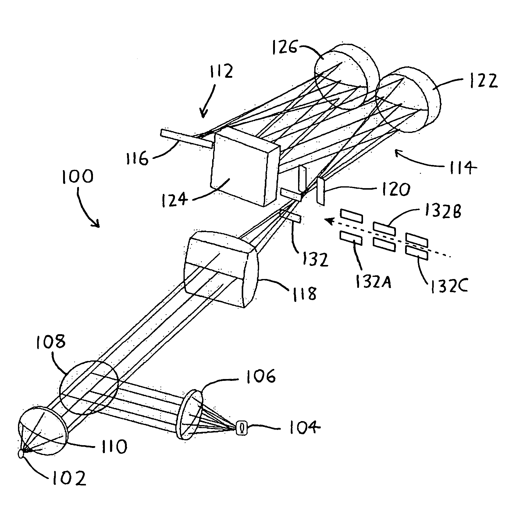
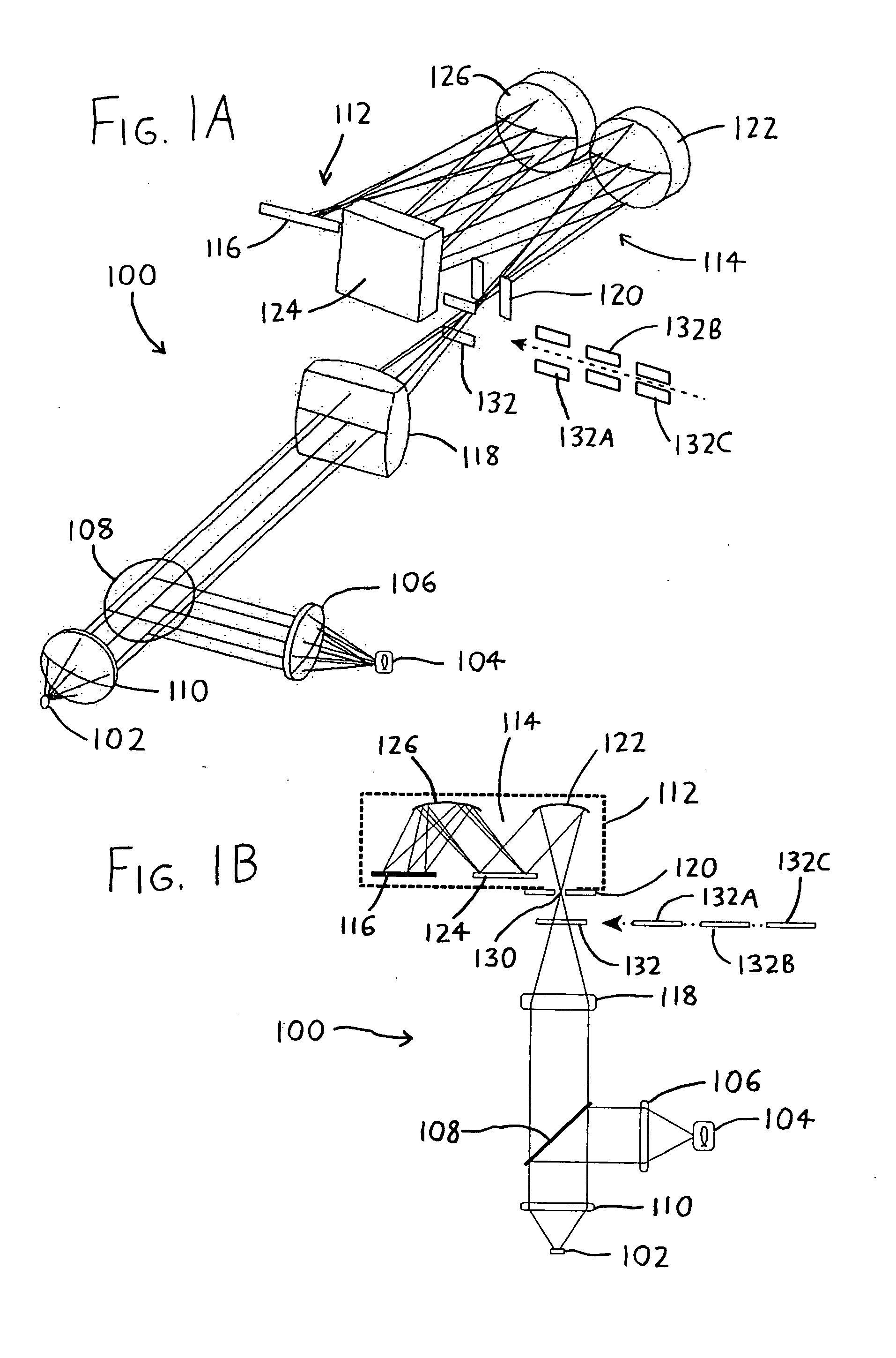
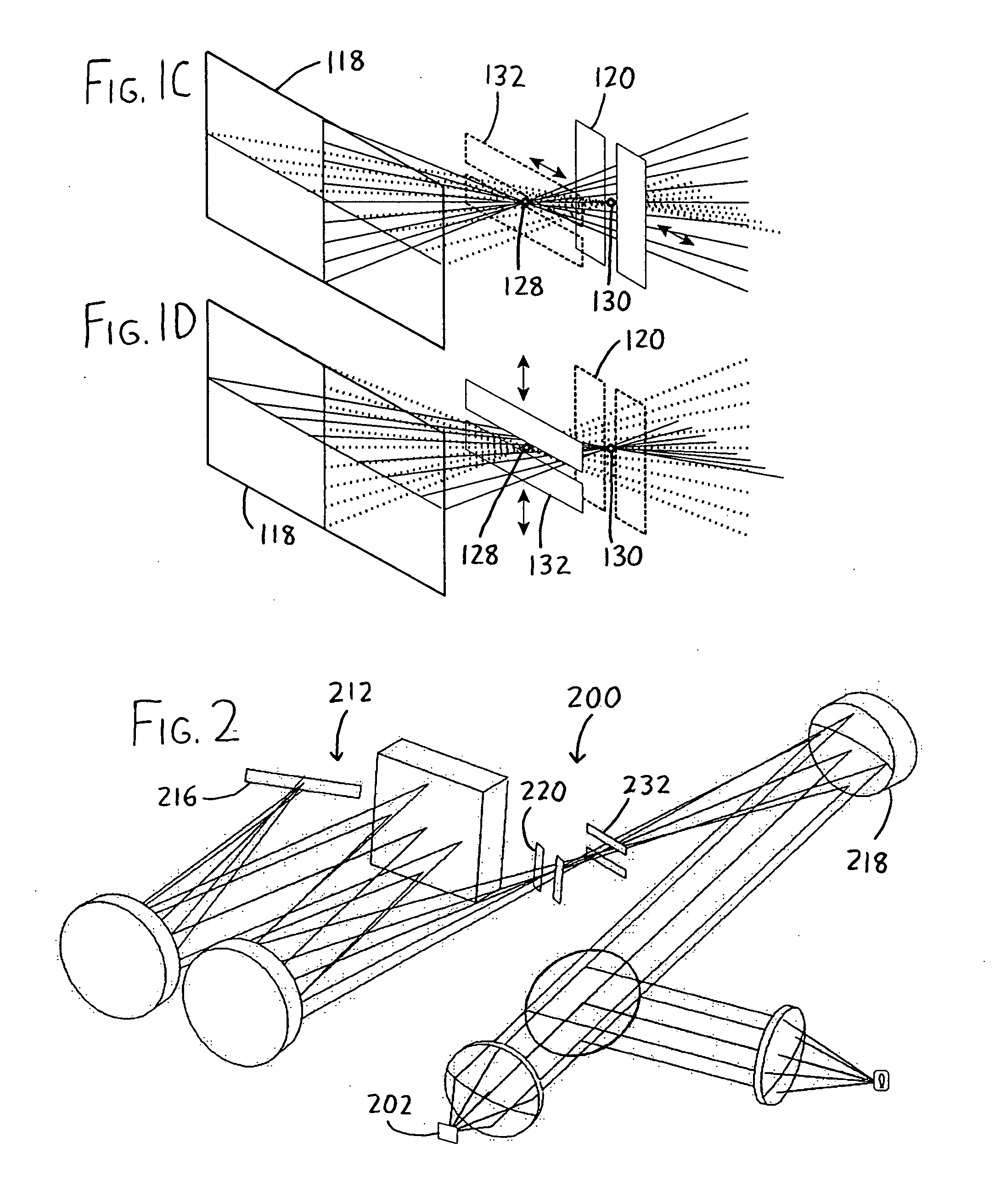
[0013]To review the invention in further detail, it should be understood that the invention can be incorporated in any appropriate preexisting spectrometer arrangement. In particular, the astigmatic optical element 118 and the dual apertures 120 and 132 can be readily implemented in preexisting spectrometer arrangements which utilize Czerny-Turner spectrographs with spherical mirrors (e.g., the Oriel MS125 spectrograph provided by Newport Corporation, Stratford, Conn.). Since the configuration of the spectrometer may vary, it should be understood that the components and arrangement of the sample mount 102, light source 104, the optical elements such as the collection lens 106, mirror 108, objective lens 110, etc., and the monochromator 114 and detector 116 may vary widely (and some of these elements may be omitted, may be replaced by functionally similar elements, and / or may be comprised of several individual elements). Additional components may be present as well, with an obvious e...


PUM


Abstract

A confocal spectrometer provides astigmatic optics which supply a monochromator or spectrograph with the image of a sample, with the astigmatic optics thereby providing separate first and second (tangential and sagittal) focal planes for the image. The monochromator / spectrograph has an entrance slit oriented along one of the focal planes, and this slit defines the spectral resolution of the monochromator / spectrograph and the field of view of the sample in one direction (in one focal plane). A supplemental slit is situated outside the monochromator / spectrograph adjacent the entrance slit, with the supplemental slit being oriented along the other focal plane. The supplemental slit therefore defines the field of view of the sample in a perpendicular direction (in the other focal plane). By varying the width of the supplemental and / or entrance slits, one may easily achieve the desired field of view.

Description

FIELD OF THE INVENTION[0001]This document concerns an invention relating generally to molecular spectrometry, and more specifically to arrangements allowing variation of the dimensions of the input aperture (pinhole, slit, etc.) to a spectrograph, and thereby vary the area / volume of a sample over which spectrometric measurements are taken, as well as the resolution of such measurements.BACKGROUND OF THE INVENTION[0002]A molecular spectrometer is an instrument wherein a solid, liquid, and / or gaseous sample is illuminated, often with non-visible light, such as light in the infrared region of the spectrum. The light reflected from, scattered by, and / or transmitted through the sample is then captured and analyzed to reveal information about the characteristics of the sample. As an example, a sample may be illuminated with infrared light having known intensity across a range of wavelengths, and the light from the specimen can then be captured for comparison to the illuminating light. Rev...

Claims


Application Information

Patent Timeline
Patent Type & Authority Applications(United States)
IPC IPC(8): G01J3/28
CPCG01J3/02G01J3/04G01J3/0289G01J3/0208
Inventor DECK, FRANCIS J.
Owner THERMO ELECTRONICS SCI INSTR LLC
Why Eureka
Try Eureka