
Optical modulation amplitude compensation

a technology of optical modulation and amplitude compensation, applied in the field of optical communication systems, can solve problems such as non-linear behavior of lasers

Active Publication Date: 2008-01-17
MACOM TECH SOLUTIONS HLDG INC
View PDF83 Cites 17 Cited by
  • Summary
  • Abstract
  • Description
  • Claims
  • Application Information

AI Technical Summary

Benefits of technology

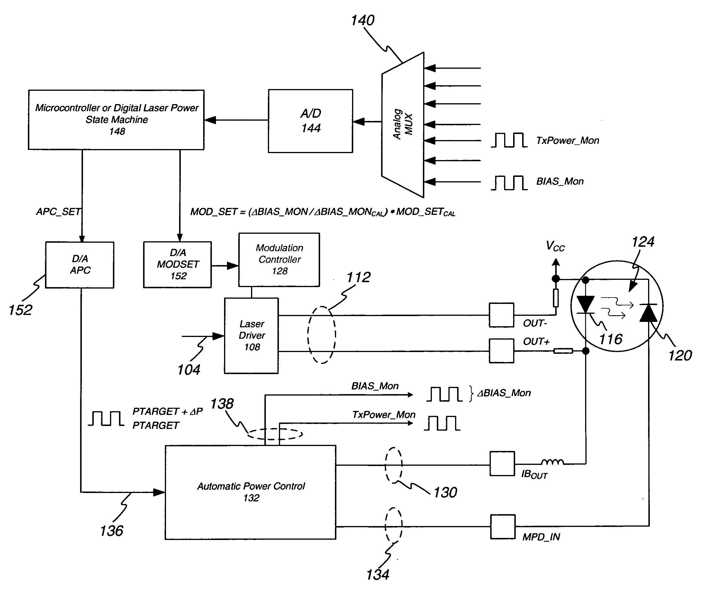
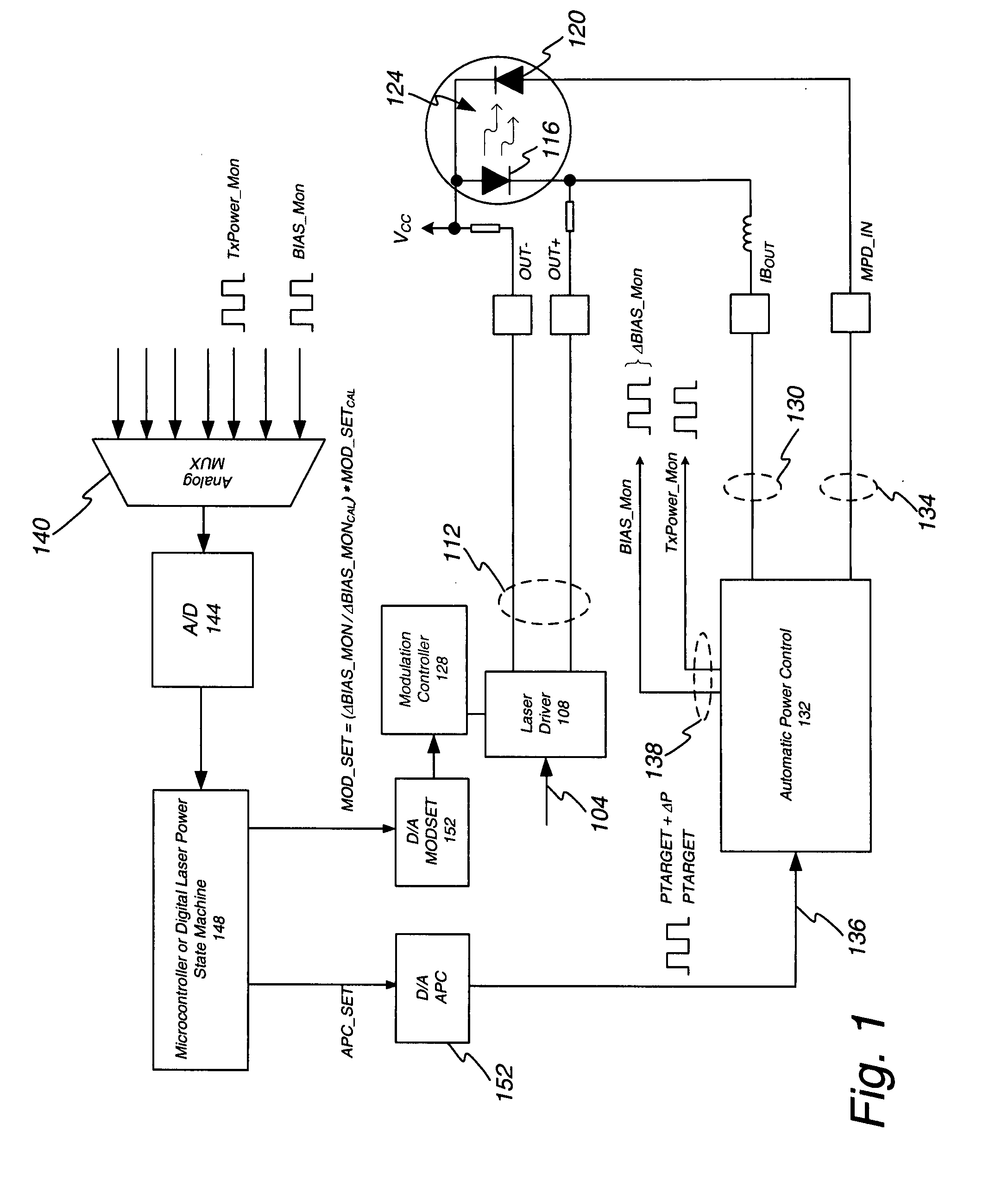
[0010] To overcome the drawbacks of the prior art and provide additional advantages, a system for optical modulation amplitude compensation is disclosed herein. In one embodiment, the system comprises an optic signal generator configured to receive a drive signal and generate an optic signal. The optic signal is detected by a detector configured to generate one or more feedback signals which are related to one or more parameters of the optic signal. Also part of this embodiment is an autom

Problems solved by technology

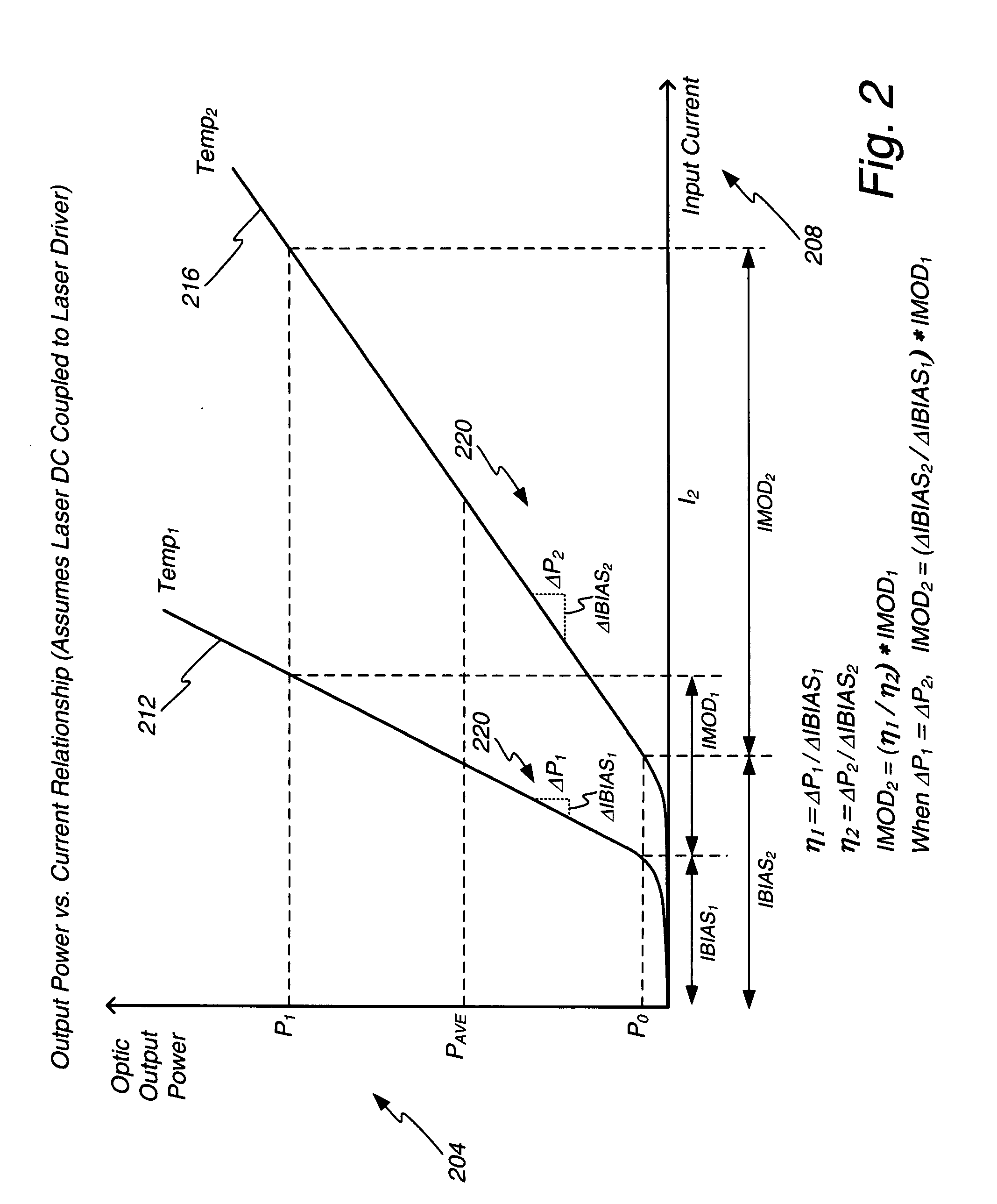
However, lasers have a non-linear behavior in terms of their threshold current (the current where stimulated emission begins) and slope efficiency (change in output power for a given change in current).

Method used


Image

  • Optical modulation amplitude compensation
  • Optical modulation amplitude compensation
  • Optical modulation amplitude compensation

Examples


Embodiment Construction

[0025] In general, the innovation disclosed herein utilizes a normal average power control loop. In the system disclosed herein the target average power is adjusted by a small percentage, and the corresponding change in bias current needed to adjust the average power level is monitored. The change in average power divided by the change in bias current is a measure of the laser's slope efficiency. Modulation current is adjusted up or down based on the change in slope efficiency compared to the slope efficiency stored at the time of module calibration.

[0026] Numerous benefits result from the design set forth herein. For example, open loop solutions do not actively monitor or control the average power and optical modulation amplitude. They rely mainly on simple temperature compensation techniques or the use of look-up tables. Look-up tables can place additional burden on the manufacturing process, likely needing to be updated with each lot of lasers. In addition, look-up tables compen...


PUM


Abstract

The power control system utilizing a normal average power control loop to control average power and modulation level of an optic signal generated by an optic signal generator. The target average power is adjusted by a small percentage, and the corresponding change in bias current needed to adjust the average power level is monitored. The change in average power divided by the change in bias current is a measure of the optic signal generator's slope efficiency. Modulation current is adjusted up or down based on the change in slope efficiency compared to the slope efficiency stored at the time of module calibration. By adjusting the modulation current, the desired optic signal output from the transmitter may be maintained.

Description

PRIOR APPLICATION DATA [0001] This application claims priority to U.S. Provisional Patent Application No. 60 / 819,256 which was filed on Jul. 6, 2006 and is a continuation-in-part from and claims priority to the following U.S. patent applications: U.S. patent application Ser. No. 11 / 244,484 filed on Oct. 5, 2005, which is a continuation-in-part of U.S. patent application Ser. No. 11 / 134,715 which was filed on May 20, 2005, which is a continuation-in-part of U.S. patent application Ser. No. 10 / 993,522, U.S. patent application Ser. No. 10 / 933,525, and U.S. patent application Ser. No. 10 / 933,561, all of which were filed Nov. 19, 2004.FIELD OF THE INVENTION [0002] The invention relates to optic communication systems and in particular to a method and apparatus for optical modulation amplitude compensation. RELATED ART [0003] Lasers are used extensively in optical communications. Data is transmitted by modulating the current through the laser, which in turn creates an optical “1” or “0” le...

Claims


Application Information

Patent Timeline
IPC IPC(8): G02F1/01
CPCH04B10/564H04B10/504
Inventor DRAPER, DANIEL
Owner MACOM TECH SOLUTIONS HLDG INC
Learn More