
Dynamic status tree facility

a dynamic status tree and facility technology, applied in computing, instruments, data processing applications, etc., can solve problems such as system resource problems, information required by monitoring systems may not be readily available, and may not be straightforward to accomplish programmatically. , to achieve the effect of low overhead communication

Inactive Publication Date: 2008-01-17
IBM CORP
View PDF22 Cites 96 Cited by
  • Summary
  • Abstract
  • Description
  • Claims
  • Application Information

AI Technical Summary

Benefits of technology

[0031] Advantages of the present invention include low overhead communication between provider processes, the tree facility and consumer processes, up level and down level support, support for changes to the system about which tree facility stores and provides information and a “drill down” capability.

Problems solved by technology

Determining the status of a software product in operation (assessing whether the product is in a “healthy state”) may not be straightforward to accomplish programmatically.
This difficulty arises, for example, in systems that support dynamic reconfiguration of the number of CPUs on the system, the amount of memory on the system or the number of products on the system.
Where the facility providing a monitoring function is itself a significant drain on the resources of the system, the monitoring function may itself create system resource problems.
Due to the complexity in software products and operating systems, the information required by a monitoring system may not be readily available.
The root cause of a problem with a system may be at a low level that is difficult to monitor on a continuous basis.

Method used


Image

  • Dynamic status tree facility
  • Dynamic status tree facility
  • Dynamic status tree facility

Examples


Embodiment Construction

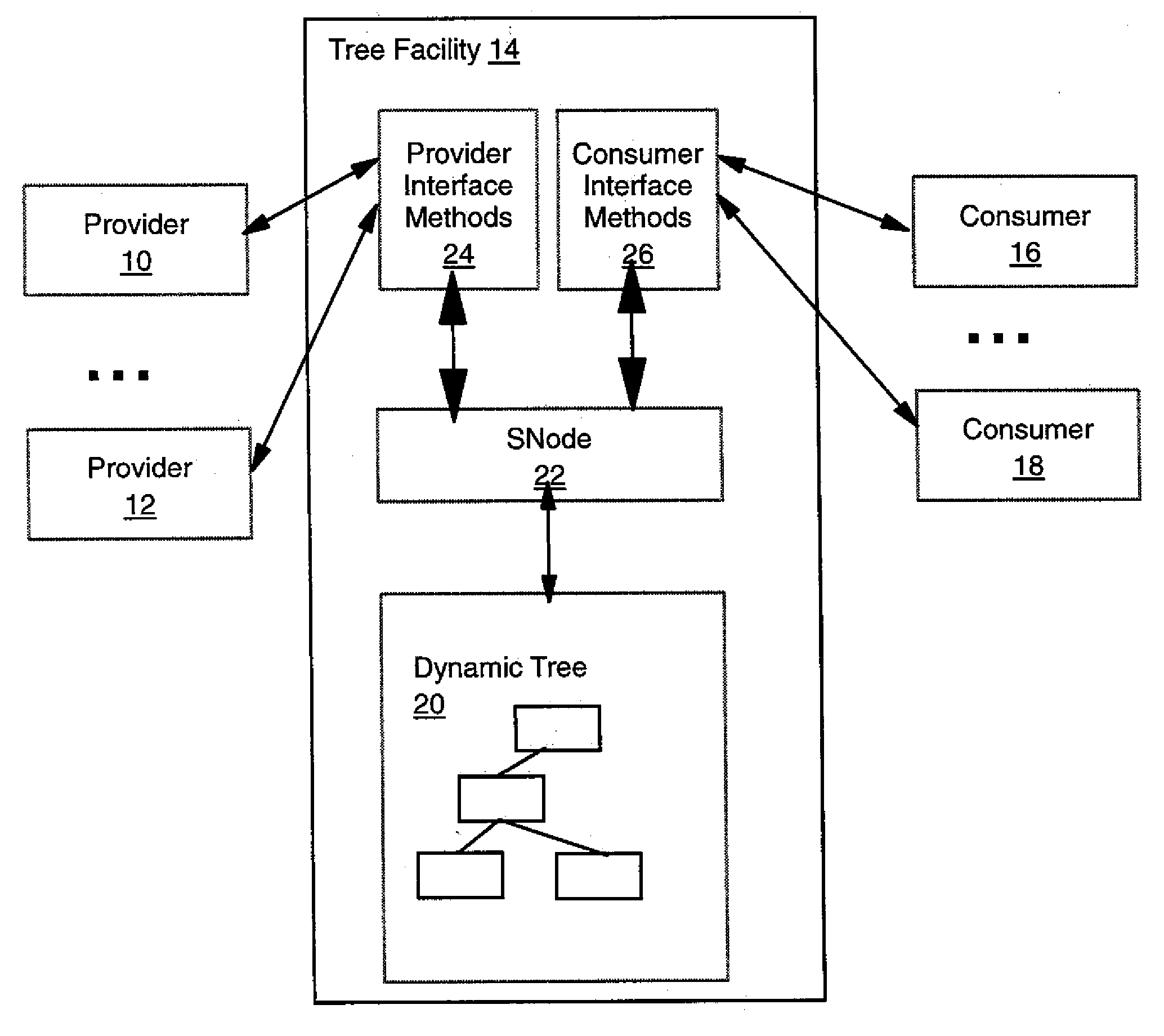
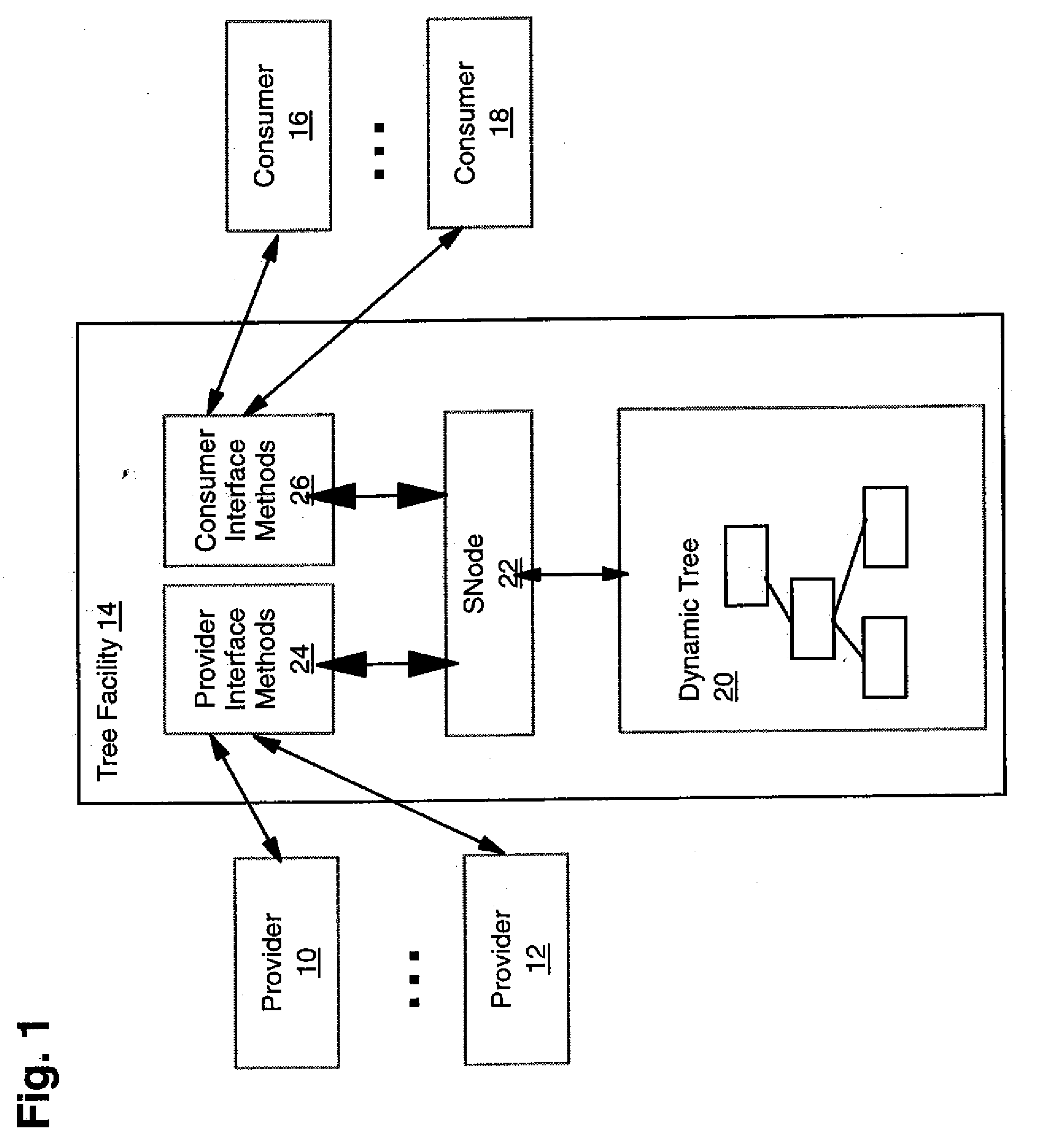
[0034] The present invention relates generally to computing systems and in particular to a system for generating and maintaining a dynamic status tree facility. The following description is presented to enable one of ordinary skill in the art to make and use the invention and is provided in the context of a patent application and its requirements. Various modifications to the preferred embodiment and the generic principles and features described herein will be readily apparent to those skilled in the art. Thus, the present invention is not intended to be limited to the embodiment shown but is to be accorded the widest scope consistent with the principles and features described herein.

[0035]FIG. 1 shows the structure of the dynamic tree facility of the preferred embodiment, in a block diagram format. Providers 10, 12 represent a potentially numerous set of processes that update tree facility 14 with information relating to a defined system. Consumers 16, 18 represent a potentially n...


PUM


Abstract

A dynamic status tree facility for providing status information about one or more systems. The facility includes a tree data structure and methods for manipulating the data structure. The facility is accessible to provider processes using a set of provider interface methods. The facility is accessible to consumer processes using a set of consumer interface methods. The tree data structure is defined by nodes stored in shared memory and attached to by way of a defined data structure made available to the provider and consumer interface methods. The nodes in the tree data structure are defined to have a control block and a variable set of export data. The export data for any one node is specified by a variable in the control block. Certain of the exported data in the tree is representable in a format selected to have one of four defined properties.

Description

CROSS-REFERENCE TO RELATED APPLICATIONS [0001] Under 35 USC §120, this application is a continuation application and claims the benefit of priority to U.S. patent application Ser. No. 10 / 196,024 filed Jul. 15, 2002 entitled “DYNAMIC STATUS TREE FACILITY”, which claims the benefit of priority under 35 USC §119 to Canadian Application No. 2,366,183, filed Dec. 21, 2001, all of which is incorporated herein by reference.FIELD OF THE INVENTION [0002] The present invention relates generally to computing systems and in particular to a system for generating and maintaining a dynamic status tree facility. BACKGROUND OF THE INVENTION [0003] The prevalence of automated systems, such as computer operating systems and database management systems, has given rise to computer systems which are themselves used to determine the status of, and to monitor, such automated systems. These program products that are used to oversee automated systems are sometimes termed monitoring or status facilities. [000...

Claims


Application Information

Patent Timeline
Patent Type & Authority Applications(United States)
IPC IPC(8): G06F7/00G06Q10/00
CPCG06Q10/06Y10S707/99944
Inventor WILDING, MARK F.ABRASHKEVICH, ALEXANDER
Owner IBM CORP
Learn More