Extendable lighted intubation stylet

Inactive Publication Date: 2008-01-24
YOSHIDA DOUGLAS K
View PDF39 Cites 50 Cited by
  • Summary
  • Abstract
  • Description
  • Claims
  • Application Information

AI Technical Summary

Benefits of technology

[0018]The extension member can be extended or retracted relative to the sheath such to increase or decrease the length of the extendable lighted intubation stylet. When utilized in retracted form, the extendable stylet is compact and may be used as a replacement for the standard stylet for routine intubations. The light source of the extendable lighted intubation stylet provides for superior visualization of the airway compared to a standard laryngoscope bulb. In extended configuration, the extendable intubation stylet is immediately available in the case of the unanticipated difficult airway and the need to look for another device in this time critical period is obviated. The extension member can be quickly extended similar to a bougie. It is then retractable in the case where the practitioner decides to use it as a bougie and then as a standard stylet or a lightwand. The exte

Problems solved by technology

This is termed the “difficult airway” and in these situations proper intubation may be difficult and ventilation of the person may fail if endotracheal tube 34 of FIG. 1 is incorrectly inserted into the person's esophagus rather than the person's trachea.
Since visibility is often partially or fully obstructed in the case of a difficult airway, intubation utilizing a standard stylet is not optimal.
Therefore, since visibility is not optimal and since the relatively large diameter of the endotracheal tube further frustrates intubation, other devices or introducers are often utilized in the difficult airway situation.
However, the bougie is approximately 70 centimeters in length and is cumbersome and is also not immediately disposed to operator's use.
Although a bougie may offer improved performance over the standard stylet, there remains a need for improved visibility and bougie 40 is also prone to twi

Method used


Image

  • Extendable lighted intubation stylet
  • Extendable lighted intubation stylet
  • Extendable lighted intubation stylet

Examples


Embodiment Construction

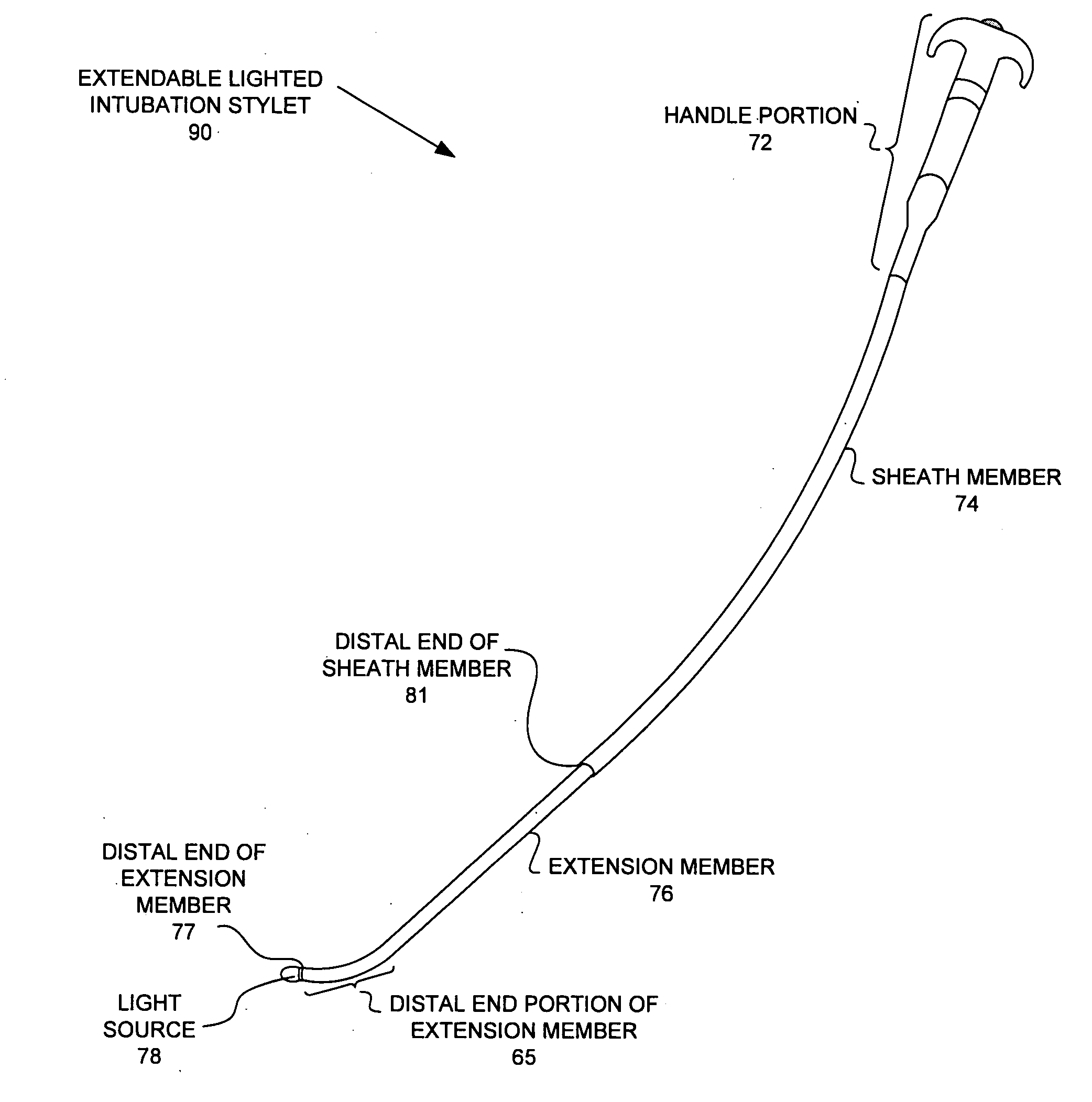
[0045]FIG. 8 is a drawing of an extendable lighted intubation stylet 69 in accordance with one novel aspect. Extendable lighted intubation stylet 69 includes a sheath member 74, an extension member 76, and a light source 78. In one embodiment, light source 78 is a light emitting diode (LED).

[0046]Sheath member 74 has a proximal end 61, a tube section, a distal end portion 85, and a distal end 81. Sheath member 74 also has a handle portion 72 which is coupled to a T-shaped grip 70 at proximal end 61 of sheath member 74. Extension member 76 is slidably coupled to sheath member 74 and has a proximal end 88, a distal end portion 65, and a distal end 77. Light source 78 is disposed upon the distal end portion 65.

[0047]Also shown in this FIG. 8 is a power supply 82. The positive terminal of power supply 82 is connected to one terminal of a switch 71. The opposite terminal of switch 71 is connected to a terminal of a resistor 87. The opposite terminal of resistor 87 is connected to one of ...


PUM


Abstract

An extendable lighted intubation stylet enables a clinician or emergency medical personnel to introduce a breathing tube into a person's trachea. The extendable lighted intubation stylet includes a handle, a switch, a sheath, an extension member, and a light source. The extension member can be extended or retracted relative to the sheath thereby increasing or decreasing the length of the extendable lighted intubation stylet. The light source provides for superior visualization of the airway compared to a standard laryngoscope bulb. In its extended configuration, the extendable intubation stylet is immediately available in the case of an unanticipated difficult airway and can be used as a bougie. The extendable stylet is lightweight and convenient because it can be folded and placed in a pocket or in a space critical location such as a field kit or portable airway bag.

Description

CROSS REFERENCE TO RELATED APPLICATION[0001]This application is based on and hereby claims the benefit under 35 U.S.C. §119 from U.S. Provisional Application No. 60 / 831,825, entitled “Extendable Lighted Intubation Stylet,” filed on Jul. 19, 2006, the subject matter of which is incorporated herein by reference.BACKGROUND INFORMATION[0002]In the course of medical care, healthcare providers often have to place an endotracheal tube into a person's airway. This process, intubation, may be necessary for artificial ventilation, protecting the airway from aspiration of stomach contents or for the delivery of anesthetics. Intubation may be performed by paramedics or military personnel in the field, in emergency departments, hospitals or in the operating room.[0003]An endotracheal tube 34 is shown in FIG. 1. An endotracheal tube has a tubular shaft 17 with a distal end 14, a proximal end 15, an inflatable cuff 12 and an inflation lumen 10. During intubation the distal end 14 of the endotrache...

Claims


Application Information

Patent Timeline
IPC IPC(8): A61M16/04
CPCA61B19/5202A61M16/0488A61M16/04A61B2017/320044A61B90/30A61M16/0418A61M16/0411
Inventor YOSHIDA, DOUGLAS K.
Owner YOSHIDA DOUGLAS K
Why Eureka
Try Eureka