Fast-acting, low leak rate active airbag vent

a technology of active airbag vents and airbags, which is applied in the direction of pedestrian/occupant safety arrangements, vehicle components, floating objects, etc., can solve the problems of inability to accurately vent, and inability to provide the necessary attenuation of the payload, etc., and achieves low leakage rate and low permeability material

Inactive Publication Date: 2008-01-24
IRVIN INDS CANADA
View PDF6 Cites 18 Cited by
  • Summary
  • Abstract
  • Description
  • Claims
  • Application Information

AI Technical Summary

Benefits of technology

[0007]In order to overcome the known problems associated with conventional passive venting systems for landing bags, the present invention provides a system and method for actively controlling the flow of air from an inflatable control volume as embodied in a parachute landing bag. According to the system, a fast acting and low leak rate vent is provided that incorporates a gas barrier assembly and an externally actuated flow initiator that allows for active venting. The gas barrier assembly includes a flexible membrane for sealing a vent opening in the landing bag, and a sheet of...

Problems solved by technology

Passive venting systems perform very poorly in a variable or uncertain landing envelope in which the necessary pressure may build up too soon or not soon enough, resulting in imprecise venting perf...

Method used


Image

  • Fast-acting, low leak rate active airbag vent
  • Fast-acting, low leak rate active airbag vent
  • Fast-acting, low leak rate active airbag vent

Examples


Embodiment Construction

[0028]In describing a preferred embodiment of the invention illustrated in the drawings, specific terminology will be resorted to for the sake of clarity. However, the invention is not intended to be limited to the specific terms so selected, and it is to be understood that each specific term includes all technical equivalents which operate in a similar manner to accomplish a similar purpose.

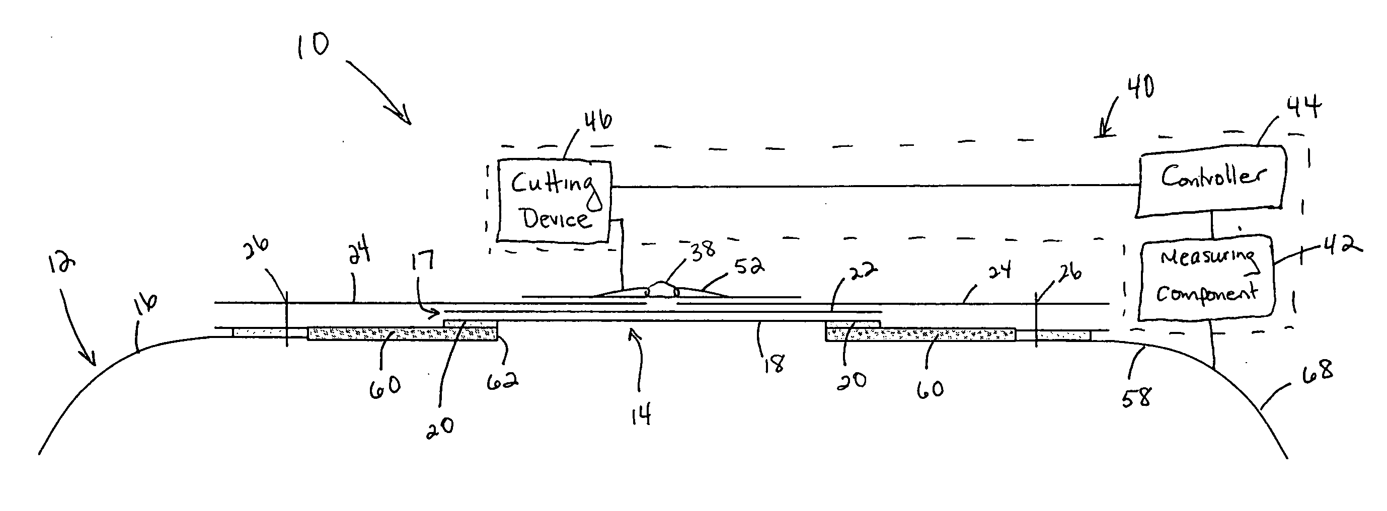
[0029]FIG. 1 illustrates a cross-sectional view of a landing bag vent, generally designated by the reference numeral 10, in accordance with the present invention. The vent 10 is formed in an airbag or landing bag, generally designated by reference numeral 12. As used herein, the phrase “landing bag” is intended to include all airbag structures used to attenuate force, whether from landing or other contact conditions in which significant forces are generated. The landing bag described herein is suitable for landing impact attenuation for large payloads including vehicles such as Unmanned Aerial V...


PUM


Abstract

A fast acting and low leak rate vent for an impact landing bag in which a vent hole is covered by a gas barrier assembly having a flexible membrane and a low gas permeability layer. A flap assembly positioned around the gas barrier assembly includes flaps that are movable between an open position in which the membrane is exposed and a closed position in which the flaps cover and reinforce the gas barrier assembly. An externally actuated flow initiator is associated with a fastening element that retains the flaps in the closed position. Upon landing, the flow initiator is activated to sever the fastening element and release the flaps and the low gas permeability layer. Thereafter, the internal pressure within the landing bag under landing forces causes the membrane to burst, releasing a flow of gas from within the landing bag to attenuate impact.

Description

BACKGROUND OF THE INVENTION[0001]1. Field of the Invention[0002]The present invention is related to the field of landing bag force attenuation and, more particularly, to a vent system and method for a parachute landing bag.[0003]2. Description of the Related Art[0004]Parachute landing bags are well known to those skilled in the art. Such airbags are used to attenuate impact force on the payload upon landing and include an airbag having a control volume of air. Upon impact with the ground, the airbag flattens somewhat to absorb the initial impact, after which a flow of air from the control volume is initiated to continue attenuating the impact.[0005]According to conventional venting approaches, the airbag is provided with one or more pressure-based burst discs as a passive means of initiating flow from the control volume. Such passive systems are activated by a build-up in pressure so as to burst when a threshold pressure inside the airbag has been reached. When employing such a syst...

Claims


Application Information

Patent Timeline
IPC IPC(8): B64C25/56
CPCB60R21/239B64D2201/00B64D1/14
Inventor TAYLOR, ANTHONY P.GARDINIER, DEBBIECOOPER, MICHELLESINCLAIR, ROBERT
Owner IRVIN INDS CANADA
Why Eureka
Try Eureka