LED power supply with options for dimming

a technology of led power supply and dimming, which is applied in the direction of electroluminescent light source, electric lighting source, lighting and heating apparatus, etc., can solve the problems of ineffective method of driving leds, significant variation in forward voltage drop, and inability to drive high-power leds using ballast resistors

Inactive Publication Date: 2008-01-24
KASTNER MARK ALLEN
View PDF12 Cites 667 Cited by
  • Summary
  • Abstract
  • Description
  • Claims
  • Application Information

AI Technical Summary

Problems solved by technology

There may also be a significant amount of variation in the forward voltage drop from one LED to another.
However, this method of driving LEDs is not very efficient, as the ballast resistor dissipates a good portion of the total power.
These reasons reflect that using a ballast resistor is not practical to drive high-power LEDs.
This approach is not a...

Method used


Image

  • LED power supply with options for dimming
  • LED power supply with options for dimming
  • LED power supply with options for dimming

Examples


Embodiment Construction

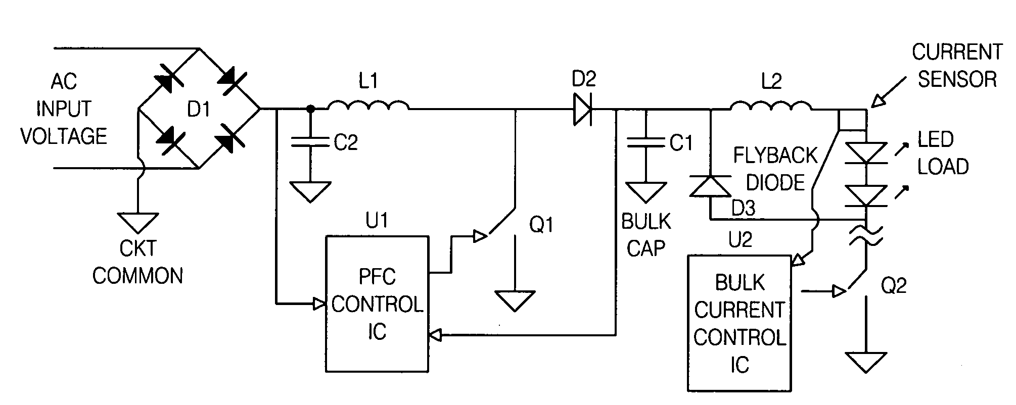
[0043] The goal of this design is to create an AC line powered LED string driver to power the LED string at a regulated current, while using only one switching / conversion stage. It must do this over a wide range of input voltages. Additionally, the circuit must do so while providing galvanic isolation between the primary and secondary circuits while presenting a power-factor-corrected (resistive) load to the incoming utility power.

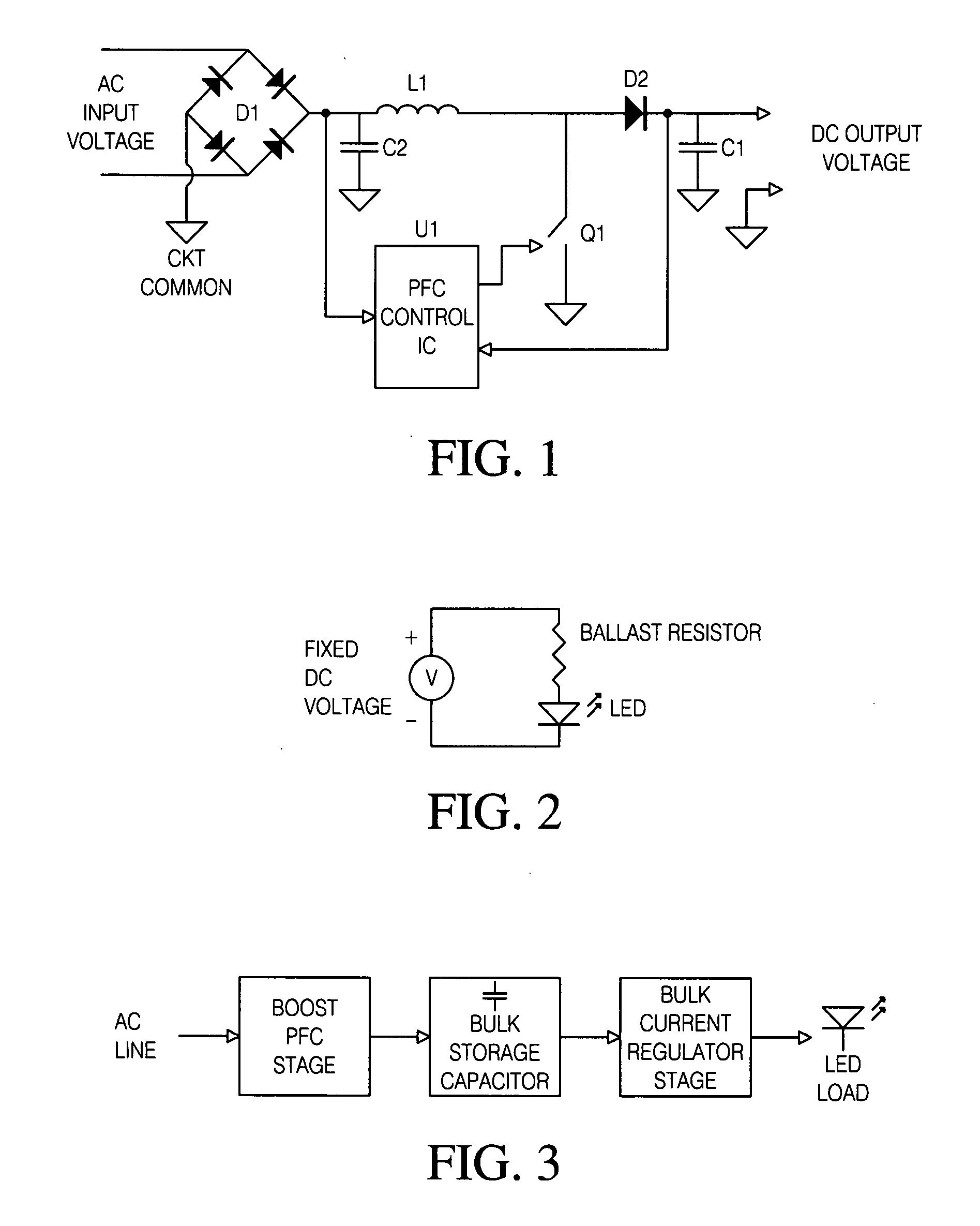
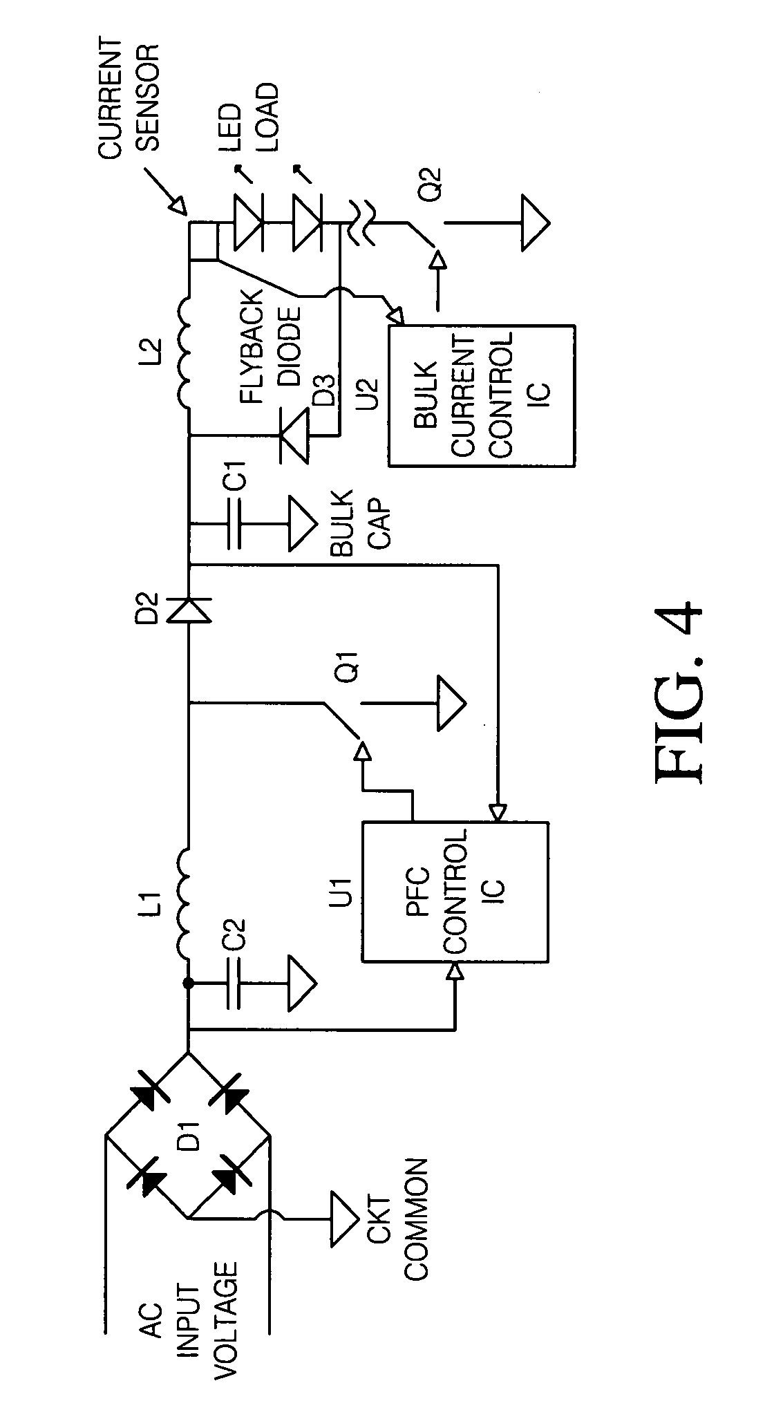
[0044]FIG. 7 shows the block diagram of a circuit designed to meet these requirements. The incoming AC voltage is full-wave rectified by bridge rectifier D1 and filtered by capacitor C2. The line-modulated (rectified) DC output voltage from the bridge rectifier is applied to the primary of flyback transformer T1. Current through the primary of T1 is switched by semiconductor switch Q1, which is controlled by power factor correction IC U1.

[0045] The primary of T1“looks” like a simple inductor when Q1 is on and primary current flows because secondary recti...


PUM


Abstract

A LED driver circuit is disclosed that has the ability to drive a single series string of power LEDs. The LED driver circuit uses a single stage power converter to convert from a universal AC input to a regulated DC current. This single stage power converter current is controlled by a power factor correction unit. Furthermore, the LED driver circuit contains a galvanic isolation barrier that isolates an input, or primary, section from an output, or secondary, section. The LED driver circuit can also include a dimming function, a red, green, blue output function, and a control signal that indicates the LED current and is sent from the secondary to the primary side of the galvanic barrier.

Description

BACKGROUND OF INVENTION [0001] Since their commercial appearance in the 1960's, light emitting diodes (LED) have become ubiquitous in electronic devices. Traditionally, LED light output was ideal for indicator applications but insufficient for general illumination. However, in recent years a great advance in the development of high-intensity LEDs has occurred. These new LEDs operate at much higher current levels than their predecessors (350 milliamps to several amperes compared to the 10-50 milliamp range for traditional LEDs). These new power LEDs produce sufficient output to make them practical as sources of illumination. [0002] Presently, the high cost of the new power LEDs renders them best suited for applications where the unique characteristics of LEDs (ruggedness, long life, etc.) offset the extra expense. However, the cost of these high power LEDs continues to fall while efficiency (light output per unit of electrical energy in) continues to rise. Predictions are that in the...

Claims


Application Information

Patent Timeline
IPC IPC(8): H05B37/02
CPCF21V23/00H05B33/0815H05B33/0851H05B33/0827H05B33/0818H05B45/10H05B45/355H05B45/38H05B45/385H05B45/46
Inventor KASTNER, MARK ALLEN
Owner KASTNER MARK ALLEN
Why Eureka
Try Eureka