Organic light emitting display

a light-emitting display and organic technology, applied in the direction of static indicating devices, instruments, cathode-ray tube indicators, etc., can solve the problems of deterioration of image quality and reduction of luminance in the organic light-emitting display, and achieve the effects of increasing reliability, high contrast ratio, and improving luminance uniformity

Inactive Publication Date: 2008-01-24
SEOUL NAT UNIV R&DB FOUND
View PDF7 Cites 5 Cited by
  • Summary
  • Abstract
  • Description
  • Claims
  • Application Information

AI Technical Summary

Benefits of technology

[0025]As such, the organic light emitting display according to the present invention can have enhanced luminance uniformity over the entire organic light emitting display, by dividing a frame into a first period and a second period, and applying an analog data of positive level to the control electrode of the driving transistor for the first period so as to allow the organic light emitting diode to emit light, while applying, for the second period, an analog data of negative level, which is opposite to the analog data applied to the control electrode of the driving transistor for the first period, so as to turn off the organic light emitting diode and simultaneously to restore the deteriorated threshold of the driving transistor.
[0026]Furthermore, an organic light emitting display is provided which can be prevented from the phenomenon of motion blur and can realize a high contrast ratio, by variously adjusting the ratio between the light emission driving period and the threshold voltage deterioration preventing period in an image display period for a frame to 1:1 or some other ratio, thus to allow a first image to be displayed naturally between one frame and the next frame.
[0027]An organic light emitting display is also provided which is applicable to various pixel circuits, in addition to the exemplary pixel circuit described in the invention, and at this time, does not require any additional wiring or element within the pixel, and can have increased reliability by adding only minimal external circuits such as frame memory and the like.

Problems solved by technology

As a result, there rises an occurrence of deterioration of image quality and reduction of luminance in the organic light emitting display.

Method used


Image

  • Organic light emitting display
  • Organic light emitting display
  • Organic light emitting display

Examples


Embodiment Construction

[0036]Hereinafter, exemplary embodiments of the present invention will be described in detail with reference to the attached drawings, to an extent that a person having an ordinary skill in the art pertained to the present invention can easily carry out the present invention.

[0037]Here, the same reference numeral was assigned for parts having similar configuration and operation throughout the specification. Furthermore, if a part is said to be electrically coupled to another part, the expression includes the case where the part is directly coupled, as well as the case where the part is coupled to another part with a different element disposed between the parts.

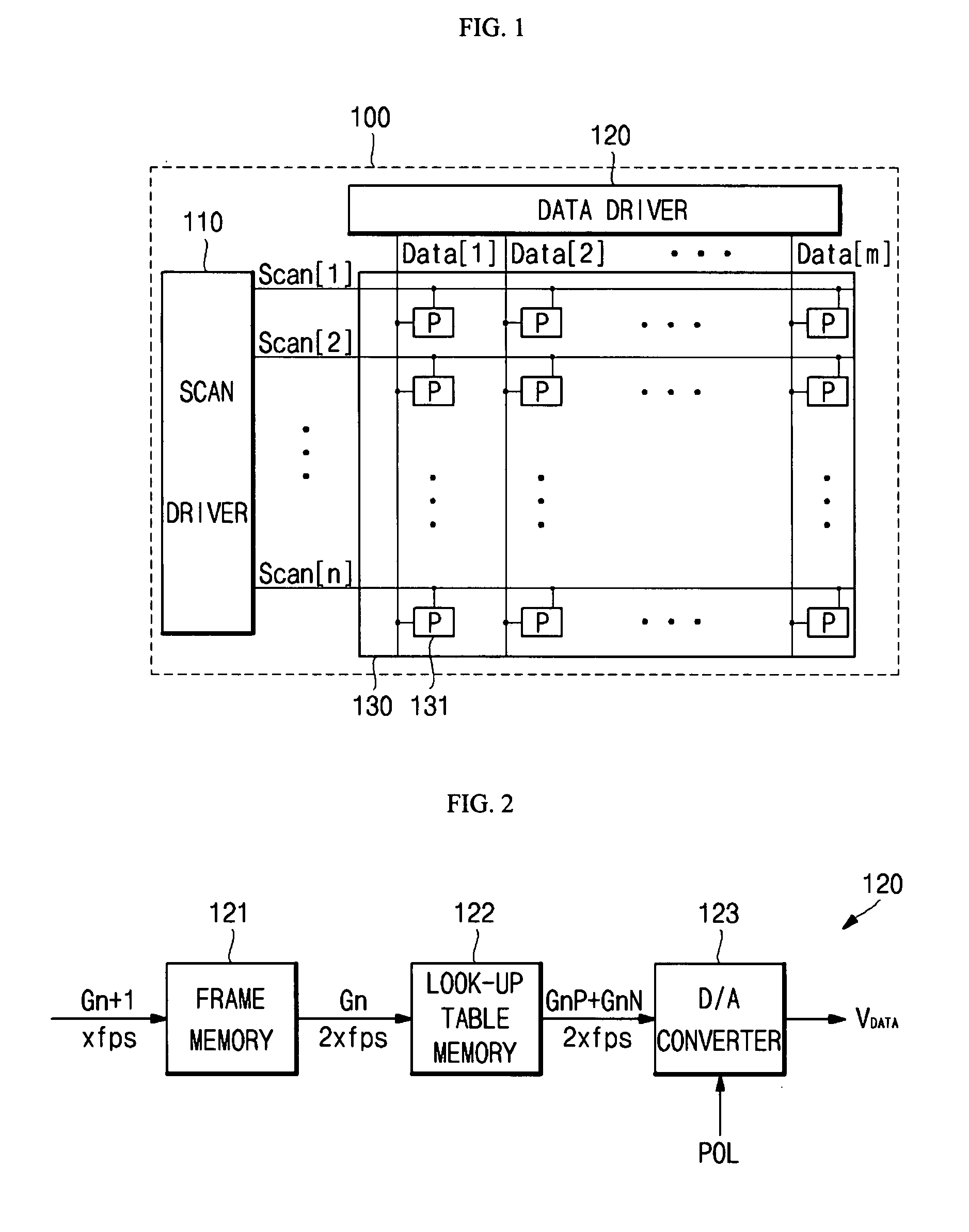
[0038]FIG. 1 shows a block diagram illustrating the configuration of an organic light emitting display according to the present invention.

[0039]Referring to FIG. 1, the organic light emitting display 100 can include a scan driver 110, a data driver 120 and an organic light emitting display panel (hereinafter, referred to as pa...


PUM


Abstract

The present invention relates to an organic light emitting display, and an aspect of the invention is to minimize the phenomenon of reduction in luminance of the organic light emitting diode display, by dividing an analog data to a positive data and a negative data, applying the same data with different polarities to the control electrode of a driving transistor, and preventing the deterioration of threshold voltage of the driving transistor.
For this purpose, the present invention discloses an organic light emitting display including a frame memory that stores data of one or more frames, doubles the frequency of the frame data, and repeatedly outputs the frame data; a look-up table memory that divides the frame data doubled and outputted from the frame memory, into two digital input signals such as a positive data and a negative data, and outputs the data; and a digital-analog converter that receives the positive data and negative data outputted from the look-up table memory, converts the data to analog data, and outputs the analog data.

Description

CROSS-REFERENCE TO RELATED APPLICATIONS[0001]This application claims priority to and the benefit of Korean Patent Application No. 10-2006-067928, filed on Jul. 20, 2006 and, the entire content of which are incorporated herein by reference.BACKGROUND OF THE INVENTION[0002]1. Field of the Invention[0003]The present invention relates to an organic light emitting display, and more particularly, to an organic light emitting display which can minimize the phenomenon of reduced luminance due to deterioration of the threshold voltage in a driving transistor, by dividing analog data to positive data and negative data, and applying the data to the driving transistor.[0004]2. Description of the Related Art[0005]Organic light emitting displays of the related art are display devices which emit light by electrically exciting a fluorescent or phosphorescent organic compound, and images are manifested by driving (N×M) entities of organic light emitting cells. Such an organic light emitting cell is ...

Claims


Application Information

Patent Timeline
Patent Type & Authority Applications(United States)
IPC IPC(8): G09G5/36
CPCG09G3/3233G09G2300/0842G09G2340/0435G09G2320/0285G09G2320/043G09G2310/0254G09G3/20G09G3/30
Inventor HAN, MIN KOOPARK, HYUN SANGLEE, JAE HOON
Owner SEOUL NAT UNIV R&DB FOUND
Why Eureka
Try Eureka