Illumination Device

Inactive Publication Date: 2008-01-24
PANASONIC CORP
View PDF8 Cites 34 Cited by
  • Summary
  • Abstract
  • Description
  • Claims
  • Application Information

AI Technical Summary

Benefits of technology

[0006] In light of the foregoing circumstances, the present invention provides an illumination device that is capable of efficiently rad

Problems solved by technology

However, the illumination device proposed by JP-2004-253364-A has a massive heat sink, and hence there i

Method used


Image

  • Illumination Device
  • Illumination Device
  • Illumination Device

Examples


embodiment 1

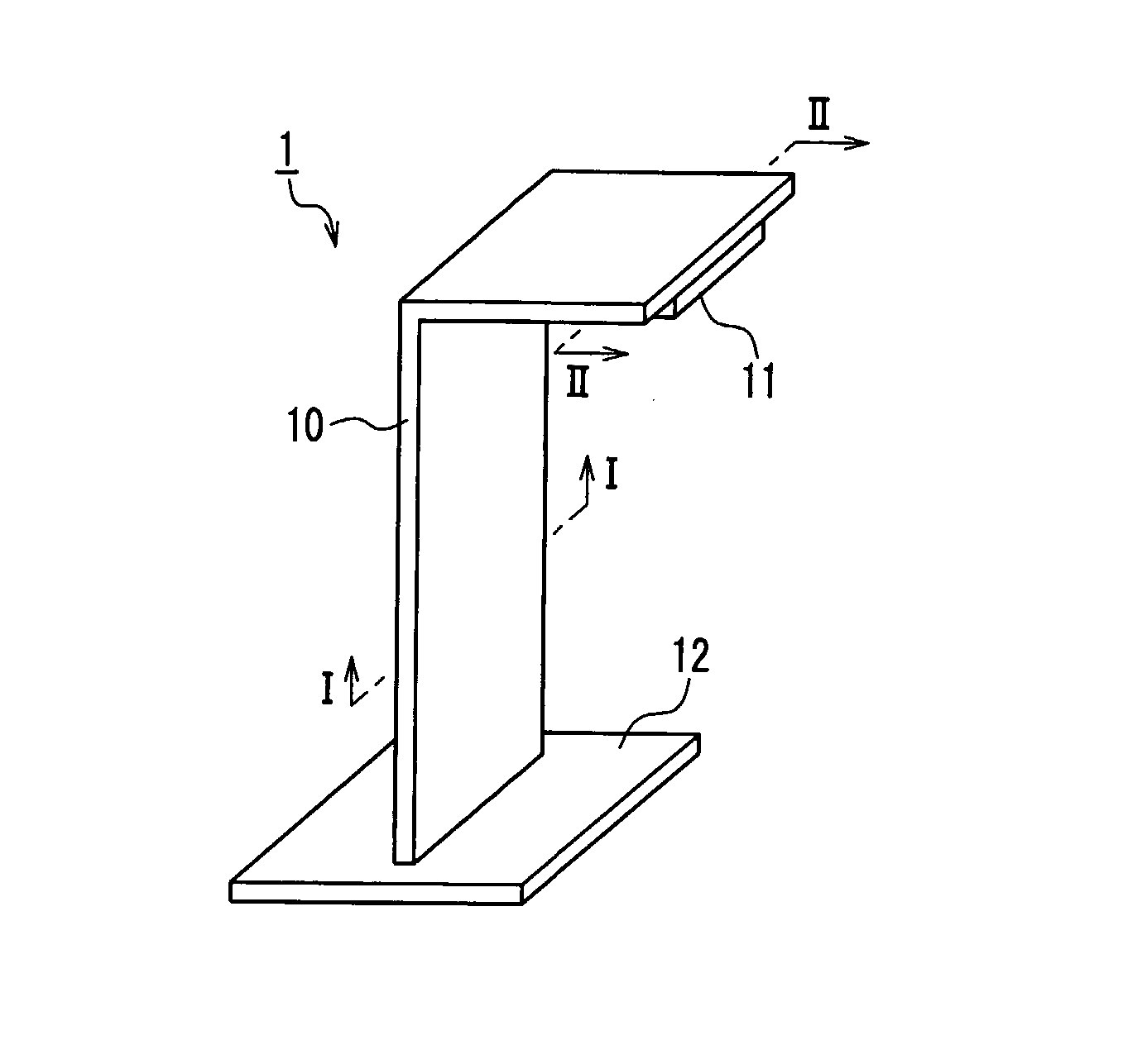
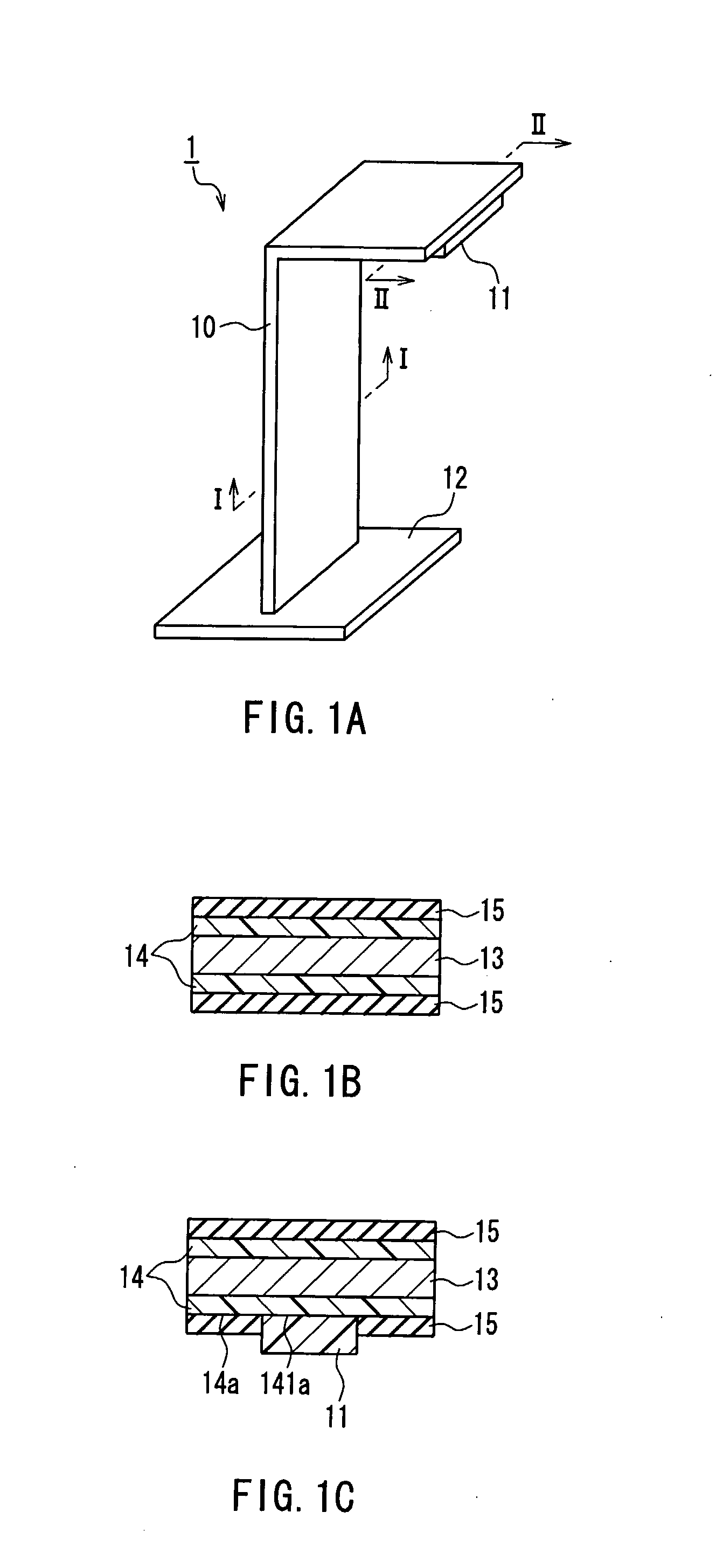
[0029] First, an illumination device according to Embodiment 1 of the present invention is described with reference to the drawings as required. FIGS. 1A to 1C to be referred to are explanatory views of a stand-type illumination device according to Embodiment 1, among which FIG. 1A is a perspective view illustrating the stand-type illumination device as a whole according to Embodiment 1, FIG. 1B is a cross-sectional view of the same taken along a line I-I shown in FIG. 1A, and FIG. 1C is a cross-sectional view of the same taken along a line II-II shown in FIG. 1A.

[0030] As shown in FIG. 1A, the stand-type illumination device 1 according to Embodiment 1 includes a frame 10 formed in a reverse L-letter shape, a light source 11 incorporating light emitting elements that is fixed to an end of the frame 10, and a base 12 fixed to the other end of the frame 10 for supporting the frame 10.

[0031] As shown in FIG. 1B, the frame 10 is formed with a support member 13 having thermal conductiv...

embodiment 2

[0033] Next, an illumination device according to Embodiment 2 of the present invention is described with reference to drawings as required. FIG. 3 referred to are explanatory views of a hanging-type illumination device according to Embodiment 2, among which FIG. 3A is a perspective view illustrating the hanging-type illumination device as a whole according to Embodiment 2, FIG. 3B is a cross-sectional view of the same taken along a line III-III shown in FIG. 3A, and FIG. 3C is a cross-sectional view of the same taken along a line IV-IV of FIG. 3A.

[0034] As shown in FIG. 3A, the hanging-type illumination device 2 according to Embodiment 2 includes a frame 20 formed in a disk shape, a light source 21, and a cord 22. The light source 21 incorporates light emitting elements and is fixed at a central portion of one principal face 20a of the frame 20. The cord 22 is mounted to a principal face of the frame 20 on a side opposite to the principal face 20a side. Further, among ends of the c...


PUM


Abstract

The present invention provides an illumination device that includes a light source (11) incorporating light emitting elements, a support member (13), an anisotropic heat conduction layer (14) formed on at least a part of a surface of the support member (13) and is configured so that a thermal conductivity thereof in a surface direction is higher than a thermal conductivity thereof in a thickness direction, and a heat radiation layer (15) formed on a part of a surface of the anisotropic heat conduction layer, and the illumination device is characterized in that the light source (11) is disposed on a part of the surface of the anisotropic heat conduction layer. This makes it possible to efficiently radiate heat generated by the light emitting elements, and provides the illumination device with high degree of freedom in designing devices that make use of the light source.

Description

TECHNICAL FIELD [0001] The present invention relates to an illumination device provided with a light source incorporating light emitting elements. BACKGROUND ART [0002] Studies on illumination devices in which light emitting elements such as light emitting diodes (LED), electroluminescence (EL) elements, etc. are used have been developed since before. Among these, an illumination device using, as a light source, a LED module obtained by mounting a plurality of LEDs on a substrate has the advantage of a long lifetime as compared with a conventional illumination device using an incandescent lamp or the like as a light source. Therefore, the foregoing device potentially may substitute for the existing illumination devices in the future. [0003] However, since the light emitting element such as a LED emits an abundance of heat at the time of emitting light, in the case where such a light emitting element is used in an illumination device, it has been necessary to provide a heat sink (hea...

Claims


Application Information

Patent Timeline
IPC IPC(8): F21V29/00F21V5/00H01L33/58
CPCF21K9/00H05K1/0203F21V29/763F21V29/2212H05K1/05F21K9/20F21V29/83
Inventor MUKAI, KENJI
Owner PANASONIC CORP
Why Eureka
Try Eureka