Wireless lans and neighborhood capture

a wireless lan and neighborhood technology, applied in the field of communication, can solve the problems of channel re-use, voice and video applications have the most stringent delay and loss requirements, and are sensitive to errors, so as to achieve the same success rate in seizing channels and eliminate unfairness

Active Publication Date: 2008-01-24
AT & T INTPROP II LP
View PDF61 Cites 57 Cited by
  • Summary
  • Abstract
  • Description
  • Claims
  • Application Information

AI Technical Summary

Problems solved by technology

Voice and video applications have the most rigorous delay and loss requirements.
Interactive data applications such as Web browsing have less restrained delay and loss requirements, but they are sensitive to errors.
For multiple-cell wireless LANs, the limited availability of channels implies that the channels must be re-used, much like in cellular communication networks.
But unlike in cellular networks, the number of channels available in wireless LANs is not adequate to ensure both contiguous coverage (which is essential for roaming) and interference-free connections at the same time.
As a result, cells assigned the same channel may experience co-channel interference in the area of overlapping coverage or near a cell's periphery.
The problem of overlapping cell coverage is acute when wireless LANs are installed without any awareness of what other wireless LANs are operating nearby.
Special MAC protocols are provided for wireless LANs because transmission is flawed by higher bit error rates, different losses are experienced on a wireless channel depending on the path on which the signal travels, and a radio node cannot listen while transmitting.
Additive noise, path loss and multipath result in more retransmissions and necessitate acknowledgements, as successful transmission cannot be taken for granted.
The inability to detect a collision as quickly as it can be detected on cable with carrier-sense multiple access with collision detection (CSMA / CD) causes more channel time to be wasted in a collision while waiting for the entire frame to transmit before the collision is detected.
Near-far capture leads to inequities, as throughput is greater for nearby stations while distant stations are starved.
This causes backoff countdown of lower priority frames to slow down and even freeze if there are higher-priority frames ready to transmit, a common occurrence in congestion.
Channel re-use in multiple-cell Wireless LANs poses a problem for the PCF and HCF, as contention-free sessions (CFSs) are generated without coordination among co-channel APs to help prevent time overlap.
The existing standard does not provide adequate coordination for contention-free sessions in such situations.
Ad hoc channel assignment methods, like Dynamic Frequency Selection of HiperLAN2, can be used but with less promising results, as the re-use distances between co-channel cells are not selected optimally.
The limited number of channels available in the unlicensed band (three channels for IEEE 802.11b) will lead to a high degree of overlap in the coverage areas of co-channel cells.
That is, the success rate of a cell in accessing its assigned channel, either by its AP generating CFSs or by (E)DCF transmissions, should be independent of its location, assuming comparable traffic loads Without fair access, transmissions can be delayed excessively in the disadvantaged cell, thus failing to meet QoS requirements.
This goal is not realized with a traditional CSMA-type of protocol, however, when channel re-use is allowed because of a neighborhood capture effect.
Given the small number of channels available, co-channel cells cannot all transmit simultaneously without causing interference on one another.
In general, there will be instability, with the channel retained by a group of cells for long time intervals.
This would have negative impact on quality of service (QoS).
The resulting neighborhood capture is deleterious to QoS because of the ensuing access delays in other co-channel cells.

Method used


Image

  • Wireless lans and neighborhood capture
  • Wireless lans and neighborhood capture
  • Wireless lans and neighborhood capture

Examples


Embodiment Construction

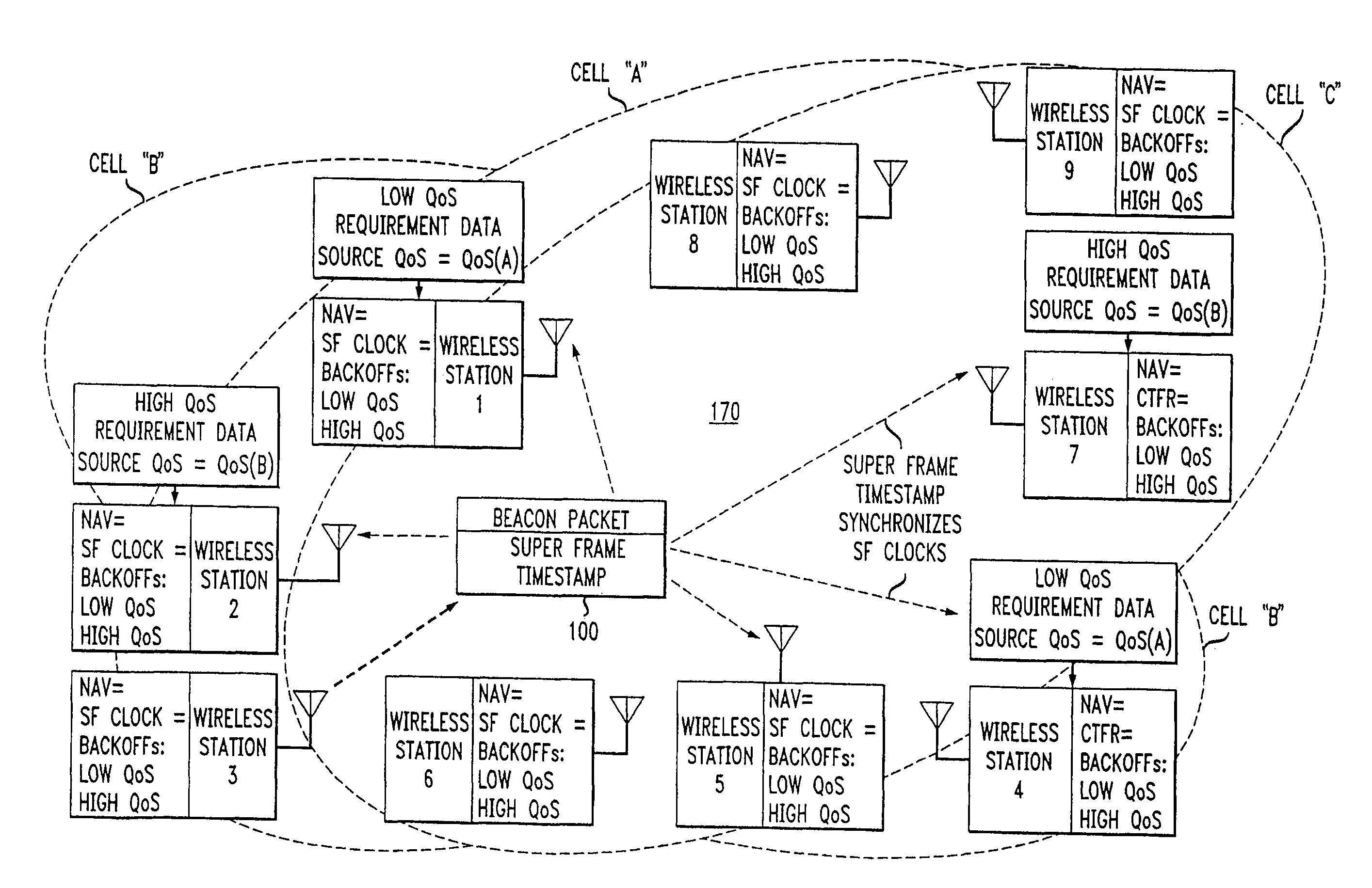
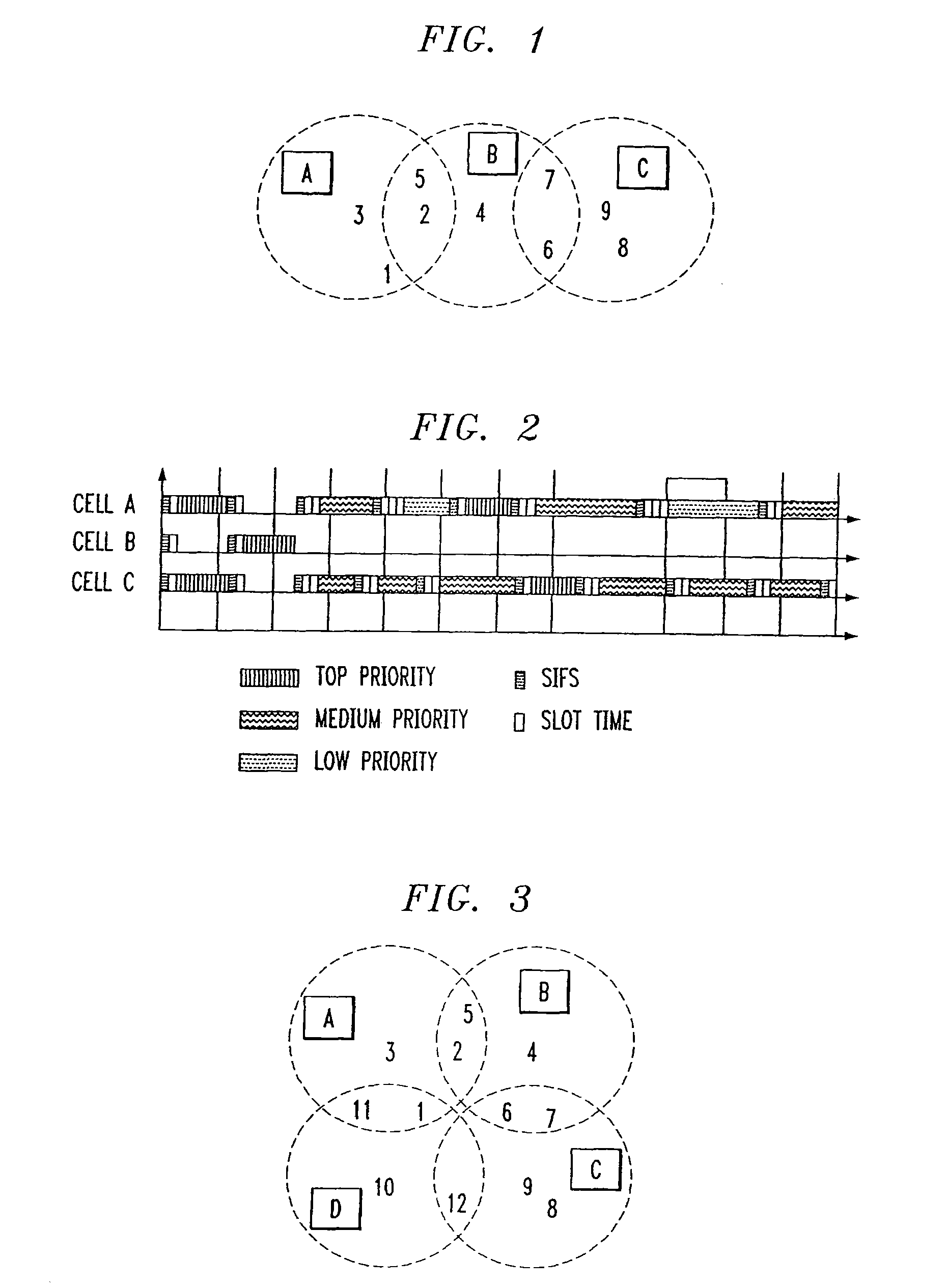
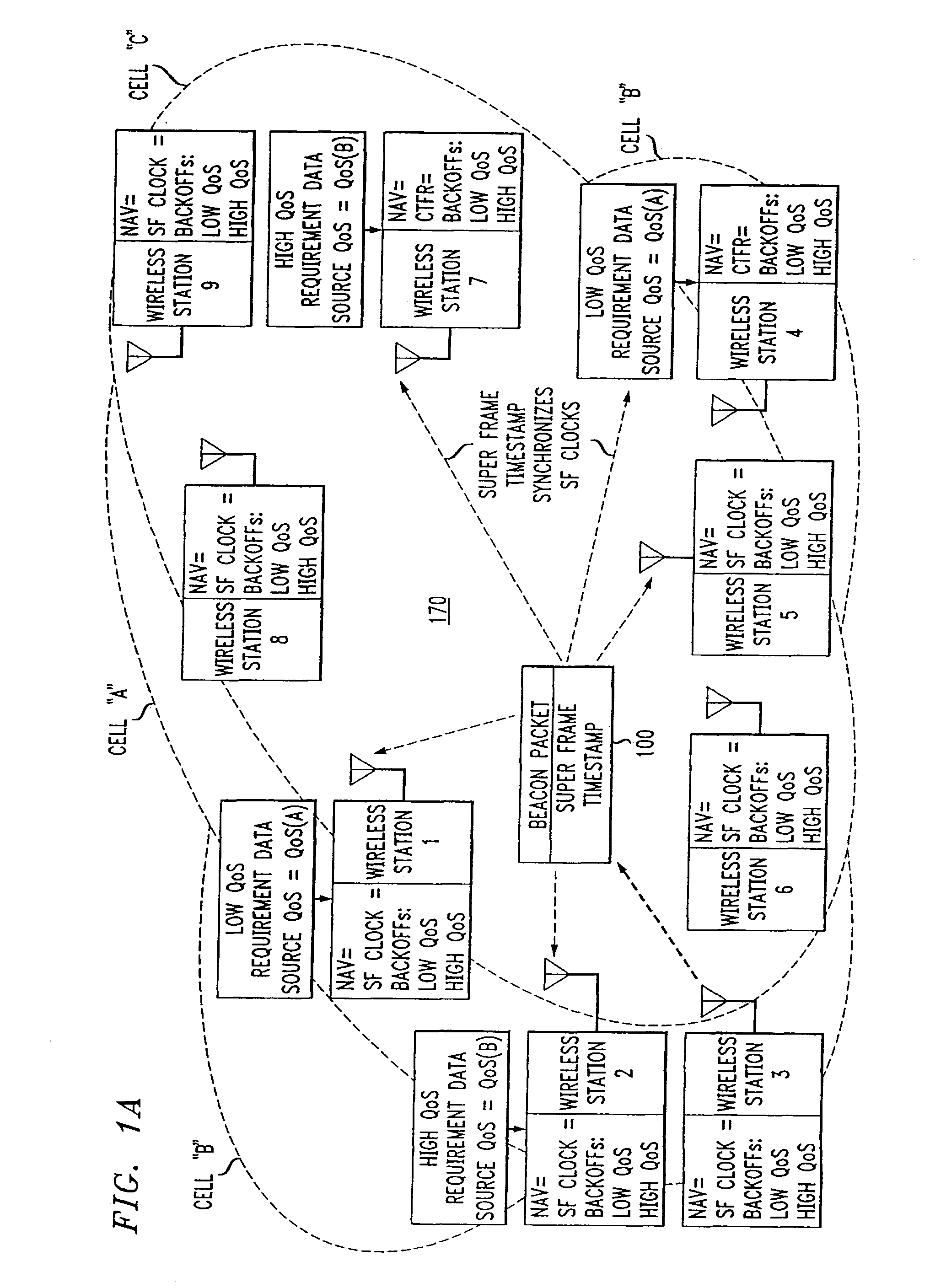
[0065] The neighborhood capture effect can be understood by considering a multiple-cell WLAN where three cells have been assigned the same channel. The cells assigned to the same channel are referred to as a co-channel group. As illustrated in FIG. 1, the three cells A, B, and C comprise nine stations. Cells are depicted as dotted circles. The stations are labeled numerically and the cells are labeled with alphabetic characters. Stations 1, 2, and 3 make up cell A with station 3 serving as the AP for cell A. Stations 4, 5, and 6 make up cell B with station 4 as cell B's AP. Stations 7, 8, and 9 make up cell C with station 9 as the AP for cell C. Cells A and C are not within interference range of each other, so they are called a re-use group. Stations in the pair of cells A-B or B-C are, however, within possible interference range of one another. In the A-B cell pair, station 2 of cell A and station 5 of cell B are both in the possible interference range of one another. Corresponding...


PUM


Abstract

Overlapped wireless LAN cells in a medium have an equal chance at establishing a session on the medium. A first member station in the first cell transmits a timing packet containing a timestamp value, which is received at a second member station in the second cell. This synchronizes member stations in the first and second cells to interrupt transmissions at a global channel release instant corresponding to the timestamp value. The member stations in the first and second cells then have the opportunity to contend for access to the medium following the global channel release instant, using a slotted CSMA / CA access method. Each of the member stations in the first and second cells has a superframe clock that is synchronized based on the timestamp value, thereby establishing a periodic global channel release instant during each of a plurality of periodic superframes. The member stations can then periodically interrupt transmissions at the periodic global channel release instant to contend for the medium. The periodic global channel release instant occurs at intervals that are sufficiently close to meet delay and jitter restrictions for time-critical voice and video applications.

Description

[0001] This application is a divisional of copending U.S. patent application Ser. No. 10 / 256,384, filed on Sep. 27, 2002, entitled WIRELESS LANS AND NEIGHBORHOOD CAPTURE (which will issue as U.S. Pat. No. 7,280,517 on Oct. 9, 2007) and which claims priority from: [0002] [1] U.S. Provisional Application Ser. No. 60 / 330,930, filed Nov. 2, 2001, entitled “HCF ACCESS MECHANISM: OBSS MITIGATION,”[0003] [2] U.S. Provisional Application Ser. No. 60 / 331,030, filed Nov. 7, 2001, entitled “‘NEIGHBORHOOD’ CAPTURE IN CSMA / CA WLANS,”[0004] [3] U.S. Provisional Application Ser. No. 60 / 331,211 filed Nov. 13, 2001, entitled “‘SHIELD’: PROTECTING HIGH PRIORITY CHANNEL ACCESS ATTEMPTS,” and [0005] [4] U.S. Provisional Application Ser. No. 60 / 342,343, filed Dec. 21, 2001, entitled “WIRELESS LANS AND ‘NEIGHBORHOOD CAPTURE’,” all of which are incorporated herein by reference. RELATED APPLICATIONS [0006] This patent application is related to U.S. patent application Ser. No. 09 / 985,257, now issued U.S. Pa...

Claims


Application Information

Patent Timeline
Patent Type & Authority Applications(United States)
IPC IPC(8): H04Q7/24H04L12/28H04L12/413H04L12/56H04W16/14H04W56/00H04W74/02H04W74/04H04W74/08H04W84/12
CPCH04W56/00H04W84/12H04W74/0808H04W74/02
Inventor BENVENISTE, MATHILDE
Owner AT & T INTPROP II LP
Why Eureka
Try Eureka