
Full Range Planar Magnetic Transducers And Arrays Thereof

a planar magnetic transducer and full-range technology, applied in the field of loudspeakers, can solve the problems of significant distortion, low sound pressure level limited acceptance and use of planar magnetic transducers in speakers, etc., and achieve the effect of relatively low diaphragm tension

Inactive Publication Date: 2008-01-24
HPV TECH
View PDF9 Cites 29 Cited by
  • Summary
  • Abstract
  • Description
  • Claims
  • Application Information

AI Technical Summary

Benefits of technology

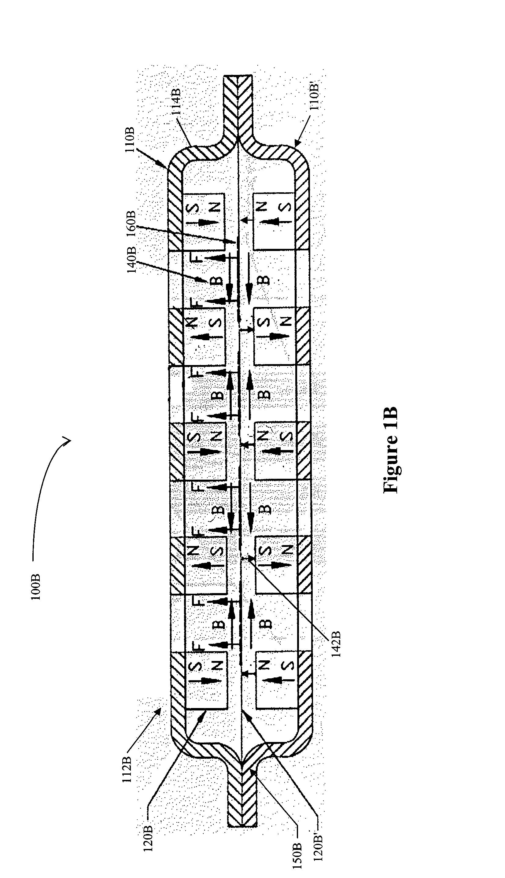
[0006] The present invention is directed to configurations and methods of full-range transducers, and especially planar magnetic transducers in which the magnets are arranged relative to each other to form large inter-magnet gaps with substantial and homogenous magnetic flux density in a plane normal to the diaphragm and with substantial magnetic flux density in a plane parallel to the diaphragm. Such arrangements together with the use of strong magnetic materials, the inter-magnet gap can be dimensioned to allow diaphragm excursions suitable for production of sound pressure levels well in excess of 120 db at 1 m distance. Such transducers are especially suitable for production of a speaker with acoustic planar source characteristics (e.g., where the variability in diaphragm tension is relatively low).

Problems solved by technology

While the theory of planar magnetic transducers is conceptually relatively simple and has been known for several decades, planar magnetic transducers have found only limited acceptance and use in speakers, mainly due to difficulties associated with limited diaphragm excursion and magnetic field strength.
Due to the above difficulties and other disadvantages, currently known speakers with planar magnetic transducers typically exhibit relatively low sound pressure levels (SPL) and often significant distortion at higher SPL.
While the excursion range of the diaphragm can be increased by increasing the distance between the magnets and the diaphragm, such increase is typically only achieved at the expense of loss in strength of the magnetic field.
Unfortunately, the increase in SPL using such known system is relatively limited.
Still further, and especially where multiple transducers are employed, inhomogeneities in physical diaphragm parameters will substantially affect accurate sound reproduction.

Method used


Image

  • Full Range Planar Magnetic Transducers And Arrays Thereof
  • Full Range Planar Magnetic Transducers And Arrays Thereof
  • Full Range Planar Magnetic Transducers And Arrays Thereof

Examples


Embodiment Construction

[0021] The inventors discovered that selected parameters dramatically affect the performance of a planar magnetic transducer, and that proper choice of such parameters will allow fabrication of high-output transducers with heretofore unknown sound pressure levels, with substantial lack of distortion, and a capability combine with additional transducers to thus form an array of planar magnetic transducers in which the array has characteristics of a plane source.

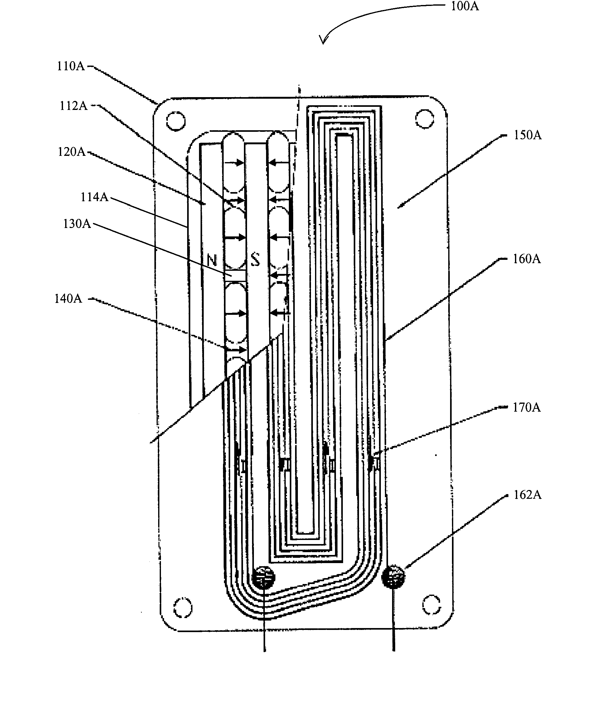
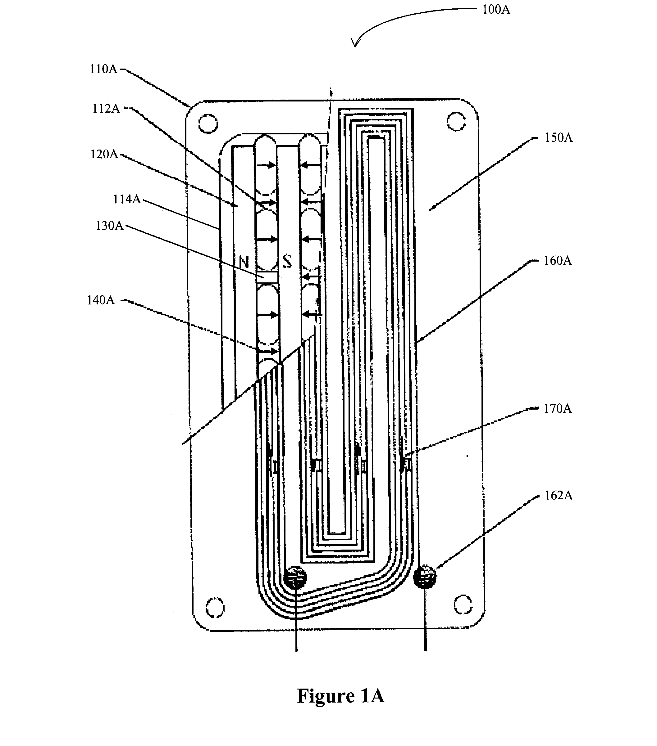
[0022] An exemplary planar magnetic transducer 100A is schematically illustrated in FIG. 1A in which a portion of the diaphragm is removed to expose underlying bar magnets, spacer elements, and other components. Here the stator frame 110A has a plurality of perforations 112A through which sound is emitted (and heat dissipated). Bar magnets 120A are coupled to the stator in a parallel fashion with alternating polarity (as indicated by North [N] and South [S]). Proper mounting alignment and distance of the magnets is maintained...


PUM


Abstract

Contemplated planar magnetic transducers include a magnet and diaphragm arrangement such that substantially homogenous vertical and high horizontal magnetic flux density is realized in the inter-magnet space. Most preferably, the diaphragm is a tensioned polymer membrane in which the voice coil covers a significant portion of the active portion of the membrane, and the magnets are rare-earth metal-type magnets of ultra-high strength. Particularly preferred planar magnetic transducers allow for exceptionally large excursion of the diaphragm in a substantially homogenous magnetic field at virtually no distortion, thereby providing heretofore unachieved sound pressure levels. Arrays of such and other transducers are disclosed that provide a full-range speaker with acoustic plane source characteristics.

Description

[0001] This application is a continuation-in-part of our allowed U.S. application with the Ser. No. 10 / 919018, filed Aug. 16, 2004, and further claims priority to our U.S. provisional application with the Ser. No. 60 / 845049, filed Sep. 15, 2006, both of which are incorporated by reference herein.FIELD OF THE INVENTION [0002] The field of the invention is loudspeakers, and especially planar magnetic speakers and arrays thereof. BACKGROUND OF THE INVENTION [0003] While the theory of planar magnetic transducers is conceptually relatively simple and has been known for several decades, planar magnetic transducers have found only limited acceptance and use in speakers, mainly due to difficulties associated with limited diaphragm excursion and magnetic field strength. [0004] Due to the above difficulties and other disadvantages, currently known speakers with planar magnetic transducers typically exhibit relatively low sound pressure levels (SPL) and often significant distortion at higher S...

Claims


Application Information

Patent Timeline
Patent Type & Authority Applications(United States)
IPC IPC(8): H04R1/00
CPCH04R9/025H04R31/006H04R9/047
Inventor SIMIDIAN, VAHAN IICOLICH, DRAGOSLAV
Owner HPV TECH
Learn More