
Small footprint modular processing system

a processing system and small footprint technology, applied in the direction of manipulators, electrical equipment, program-controlled manipulators, etc., can solve the problems of time-consuming assembly, manufacturers may not be able to absorb the cost of r&d with the typical production tool used in this manner, and start-ups or other interested parties may be prohibited from r&d

Inactive Publication Date: 2008-01-24
APPLIED MATERIALS INC
View PDF24 Cites 12 Cited by
  • Summary
  • Abstract
  • Description
  • Claims
  • Application Information

AI Technical Summary

Benefits of technology

[0008]Embodiments disclosed herein describe a small footprint modular transfer chamber for transferring substrates, such as semiconductor wafers. The transfer chamber is capable of coupling with a plurality of process chambers that may be a combination of 200 mm and 300 mm process chambers.
[0009]In one embodiment, a small footprint transfer chamber is described. The transfer chamber includes a body including an interior volume bounded by at least four sidewalls, a substrate transfer port formed through each of the sidewalls, and a transfer robot positioned within the interior volume, the transfer robot configured to withstand temperatures in excess of 100 degrees C.
[0010]In another embodiment, a small footprint transfer chamber is described, which includes at least three sidewalls adapted to couple to a plurality of 200 mm and / or 300 mm process chambers, and a robot having an end effector suitable for transferring 200 mm and 300 mm substrates, wherein the transfer chamber defines a plan area less than about 1000 square inches.
[0011]In another embodiment, a small footprint transfer chamber is described, which includes a body including an interior volume bounded by at least three sidewalls adapted to couple to a plurality of 200 mm and / or 300 mm process chambers, a substrate transfer port formed through each of the sidewalls, and a transfer robot positioned within the interior volume, the transfer robot configured to withstand temperatures in excess of 100 degrees C, wherein the robot includes an end effector suitable for transferring 200 mm and 300 mm substrates.

Problems solved by technology

The typical production tool has many large and heavy components, is time consuming to assemble, and generally requires a permanent or semi-permanent space in a clean room as it cannot be moved easily.
Due to this interruptive testing, which results in extensive downtime and may endure one day or longer, a manufacturer may not be able to absorb the cost of research and development (R&D) with the typical production tool used in this manner.
Further, start-ups or other interested parties may be prohibited from R&D due to the high initial capital outlay for the production tool and its required clean room space.
Also, a manufacturer may desire to reconfigure the tool, which may be difficult due to the platform arrangement of the typical production tool.

Method used


Image

  • Small footprint modular processing system
  • Small footprint modular processing system
  • Small footprint modular processing system

Examples


Embodiment Construction

[0022]Embodiments of the invention provide a transfer chamber that allows users, such as manufacturers or researchers, among others, to build a processing system that is highly modular, thus allowing the manufacturer or researcher to purchase processing equipment on an as-needed basis to build a production system without a significant capital expenditure. The transfer chamber and the modularity of the processing system also allows users to build the system to any desired configuration or reconfigure the processing system as the need arises.

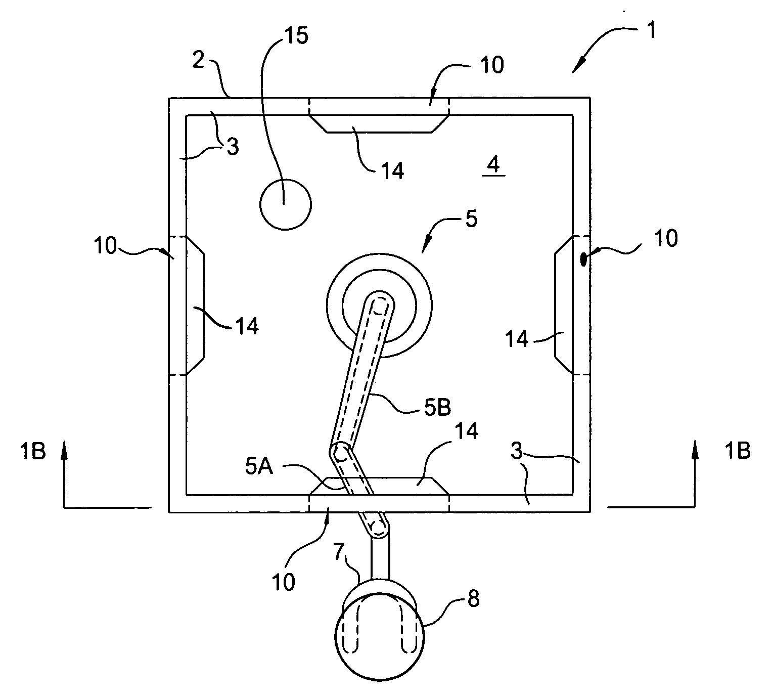
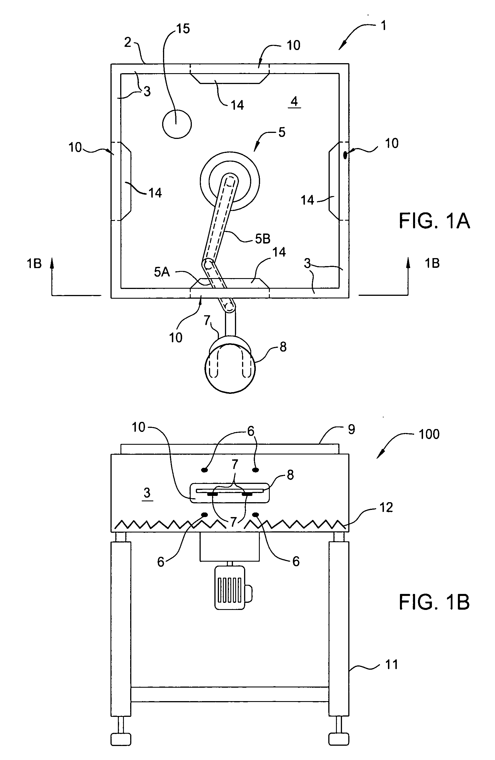
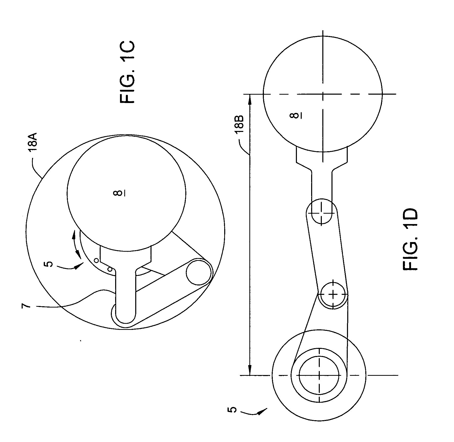
[0023]FIG. 1A is a top view of one embodiment of a transfer chamber 100 that, in one embodiment, forms the foundation of a modular processing system. The transfer chamber 100 includes a body 2 bounded by sidewalls 3. A transfer robot 5 is disposed in an interior volume 4 of the body 2. The transfer robot 5 is located at substantially a center-line of the transfer chamber 100. The transfer robot 5 includes at least one end effector 7 configured to ...


PUM


Abstract

A method and apparatus for a modular processing system is described. The apparatus includes a transfer chamber as the foundation for the system and includes sidewalls adapted to receive at least three 200 mm and / or 300 mm process chambers. The transfer chamber includes a robot capable of withstanding high temperatures and is configured to transfer 200 mm and 300 mm substrates. The modularity of the transfer chamber is highly transportable and provides a research and development platform at a low cost of ownership and may be modularly built into a production system as additional chambers and peripheral hardware is added.

Description

BACKGROUND OF THE INVENTION[0001]1. Field of the Invention[0002]This invention relates to semiconductor processing equipment. More particularly, the invention relates to a semiconductor processing system having modular capabilities and a small footprint.[0003]2. Description of the Related Art[0004]The semiconductor fabricating field is a highly dynamic industry that continues to meet evolving consumer demands while overcoming tremendous engineering obstacles. While there is a constant drive to make electronic devices smaller than the state of the art, the majority of device manufacturers rely on proven production tools to produce proven and marketable state of the art devices to meet consumer demand at a reasonable profit.[0005]One commonly utilized production tool is a cluster-type tool, which generally includes a plurality of process chambers coupled to a central transfer chamber. Another type of conventional production tool is an in-line system, which generally includes a plurali...

Claims


Application Information

Patent Timeline
Patent Type & Authority Applications(United States)
IPC IPC(8): H01L21/677
CPCH01L21/67196B25J9/042B25J9/106B25J11/0095H01L21/67742H01L21/68707
Inventor MYO, NYI OOPOPPE, STEVENWHITE, ANTHONYKRISHNA, NETY M.
Owner APPLIED MATERIALS INC
Learn More