Positioning device for the positioning of pipettes

a positioning device and pipette technology, applied in the direction of liquid dispensing, material testing goods, chemical methods analysis, etc., can solve the problems of not working accurately enough for the present application, and achieve the effect of convenient integration of the system, increased precision, and precise pipetting

Active Publication Date: 2008-01-24
STRATEC BIOMEDICAL AG
View PDF10 Cites 100 Cited by
  • Summary
  • Abstract
  • Description
  • Claims
  • Application Information

AI Technical Summary

Benefits of technology

[0008] Proceeding from this state of the art, invention enables precise pipetting by means of a compact design of the positioning device.
[0009] In this achievement the sliding carriage used transversely to the working area is at the same time employed to accommodate the pipetting apparatus, above all the pump drive and the pump chambers being accommodated by and integrated in the sliding carriage. This means that there is no need for hose connections and externally situated pumps and valves. Since there is no longer a need for hose connections that are conventional in the state of the art and are expensive and time-consumimg to lay and conduct, such a design facilitates integration of the system. The reduction in the number of the said connections and lines also makes a contribution to increased precision. The dead volume between the pump and the pipetting needle is decisive for the precision of each pipetting system. Through the integration of the pump in the sliding carriage, the dead volume of several milliliters—(as is the case in conventional pipetting systems where hose lengths are at least two meters and an inside diameter is 1.5 mm where the said dead volume can rapidly amount to in excess of three milliliters)—is reduced to clearly less than one milliliter substantially through the connecting bore in the valve disk.
[0010] A plurality of pump chambers and/or a plurality of pumps with different volumes are preferably integrated in the sliding carriage. This means that, on the one hand, the useful pipetting volume range can be extended, and, at the same time, as long as there is a plurality of pumps, the suitable pump can be selected for the desired pipetting volume. Consequently, this allows optimized pipetting precision o

Problems solved by technology

An additional disadvantage of using the micro pumps is that t

Method used


Image

  • Positioning device for the positioning of pipettes
  • Positioning device for the positioning of pipettes
  • Positioning device for the positioning of pipettes

Examples


Embodiment Construction

[0028] The invention is now described in more detail with reference to the attached drawings. The embodiments, however, are only examples that are not to restrict the inventive concept to a specific arrangement.

[0029] Before the invention is described in detail, it must be pointed out that it is not restricted to the respective components of the apparatus and the respective method steps, as the said components and methods can vary. The terms used in this case are purely used to describe particular specific embodiments and are not used in a restrictive manner. In addition, if in the description or in the claims the singular or non-specific articles are used, this also refers to the plural of the said elements unless the overall context specifically makes clear something to the contrary.

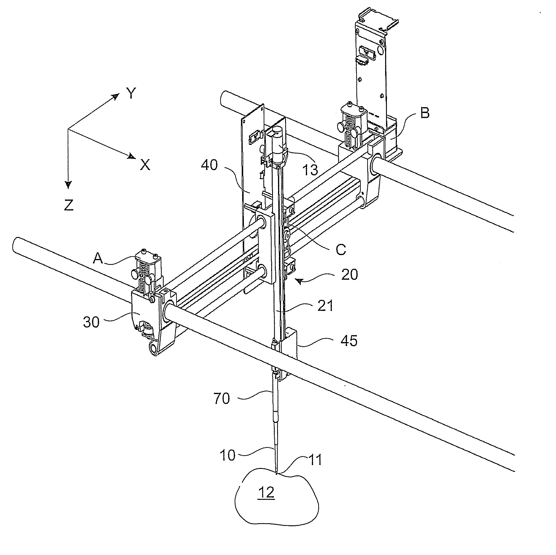
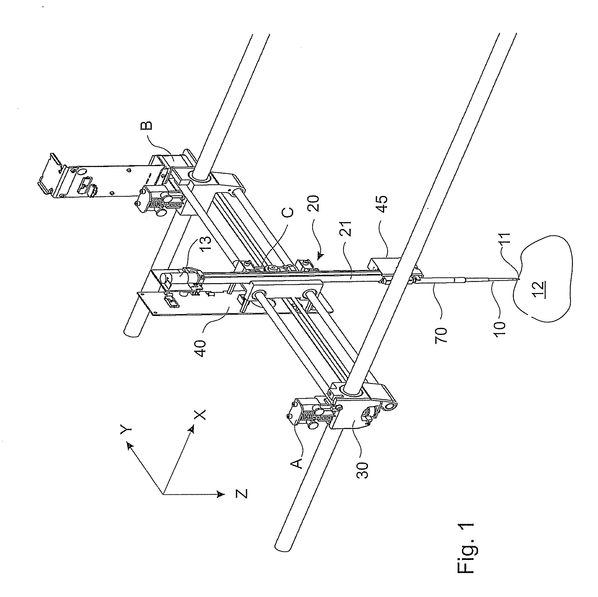
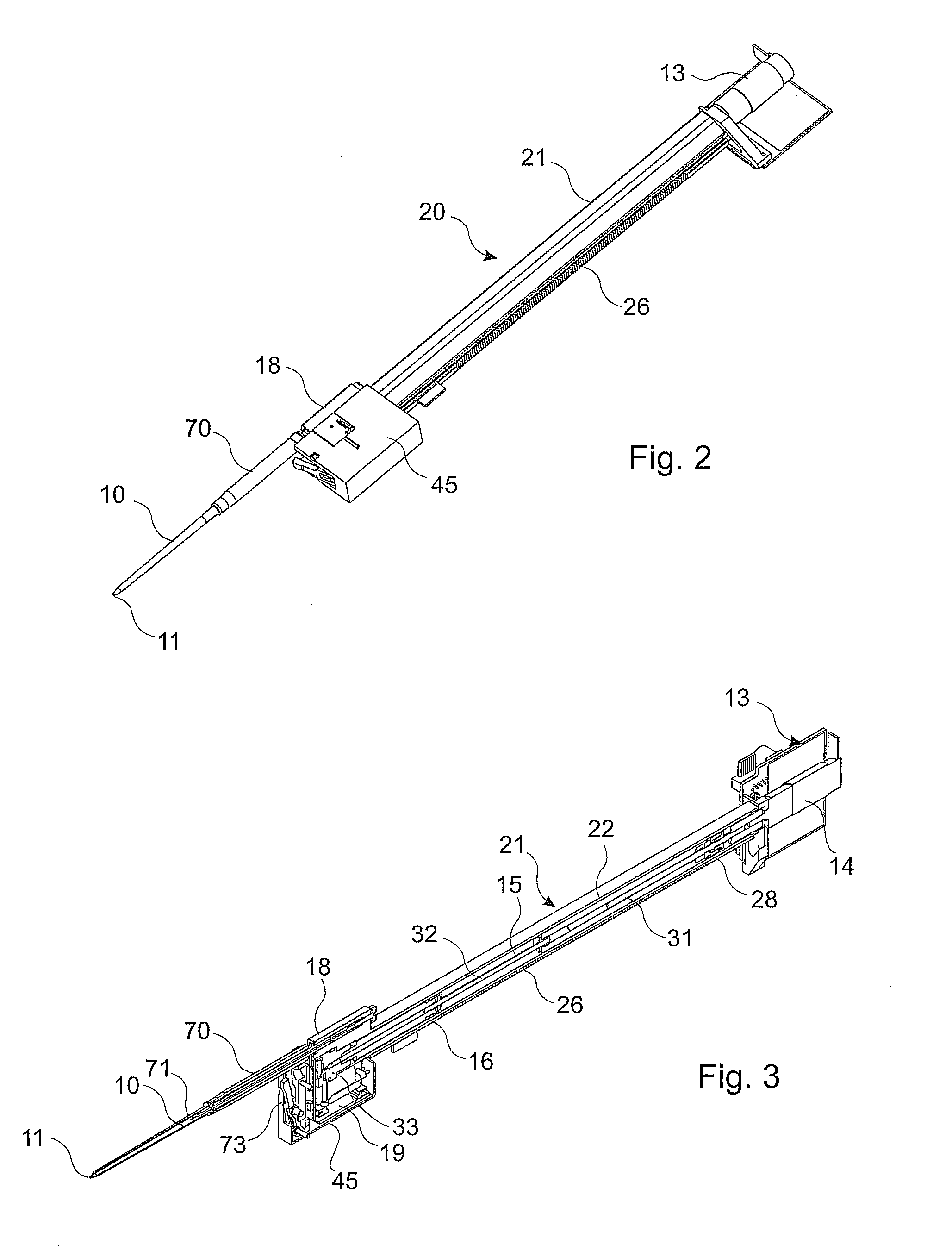
[0030] The Figures show a positioning device for positioning pipettes 10 of a pipetting apparatus, more especially for aspirating and dispensing processes in the medical-technical area, wherein in a ...


PUM


Abstract

“A positioning device is provided for positioning pipettes in medical-technical applications including at least one pipetting apparatus with at least one pipette as well as several drive units for positioning a pipette tip and for moving it over a working area and transversely to a working area, a sliding carriage that is moveable transversely to the working area supports the pipette, at least one pump drive with at least one pump and at least one pump chamber is provided for aspirating or dispensing a medium, such that by providing the at least one pump drive with pump and at least one pump chamber integrated in the sliding carriage that is moveable transversely to the working area, the design of the positioning device becomes compact and precise pipetting is achieved.

Description

CROSS REFERENCE TO RELATED APPLICATIONS [0001] The present application claims priority from German patent 10 2006 034 245.3, filed on Jul. 21, 2006, the disclosure contents of which are herewith also expressly made the object of the present invention. TECHNICAL FIELD OF THE INVENTION [0002] The invention relates to a positioning device for positioning pipettes or respectively pipetting tips, more especially for the aspirating and / or dispensing of media in medical-technical applications in accordance with the preamble of claim 1. BRIEF DESCRIPTION OF RELATED ART [0003] DE 691 26 690 T2 and the associated EP 0 478 753 B1 make known an automated molecular biology laboratory, in which a multiple-axis positioning device is used. The Cartesian robot that is used for positioning with a plurality of sliding carriages is described in EP 0 478 753 B1, column 13, line 18 to column 16, line 12. A third sliding carriage controlled via a toothed rack is displaceable in the vertical direction on t...

Claims


Application Information

Patent Timeline
IPC IPC(8): B01L3/02
CPCG01N35/109G01N35/1011
Inventor TRUMP, MARTIN
Owner STRATEC BIOMEDICAL AG
Why Eureka
Try Eureka