
Liquid-containing film structure

a film structure and liquid technology, applied in the field of liquid-containing film structure, can solve the problems of low production efficiency, lack of structure integrity and depth control, and certain disadvantages of continuous liquid phase structure, and achieve the effect of improving mechanical properties and structural integrity of film structur

Inactive Publication Date: 2008-01-24
SIPIX IMAGING INC
View PDF20 Cites 65 Cited by
  • Summary
  • Abstract
  • Description
  • Claims
  • Application Information

AI Technical Summary

Benefits of technology

[0019]Using the film structure, a liquid composition is filled into individual microcups and the filled microcups are top-sealed. The size of the microcups can be predetermined and controlled. In addition, the microcup wall is in fact a built-in spacer to keep the top and bottom substrates apart at a fixed distance. The mechanical properties and structural integrity of the film structure are significantly improved. Furthermore, the use of the film structure eliminates the need of an edge seal adhesive required in the formation of a display panel. More importantly, the microcup-based film structure enables a format flexible manufacturing process wherein the process produces a continuous output of the film structure in a large sheet format which can be cut into any desired sizes afterwards.

Problems solved by technology

However, such a continuous liquid phase structure suffers certain disadvantages.
For example, it lacks structure integrity and depth control, especially when the plates are flexible substrates.
In addition, this type of structure is not format flexible for production and, if hard surface plates are involved, batch manufacturing is required which results in low production efficiency.
It could be challenging to control the size of the microcapsules to be within a desired range.
In addition, the capsule wall usually does not provide good mechanical support for structural integrity, especially with flexible substrates.
Material selection is another issue with the microencapsulation technique.
In many cases, extra chemical(s) are necessary to stabilize the dispersed phase; the extra chemical(s), however, could be detrimental to the final product.

Method used


Image

  • Liquid-containing film structure
  • Liquid-containing film structure
  • Liquid-containing film structure

Examples


Embodiment Construction

1. Film Structure

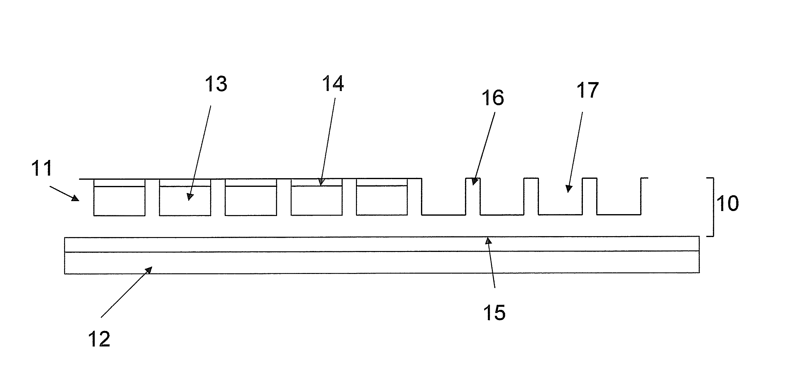
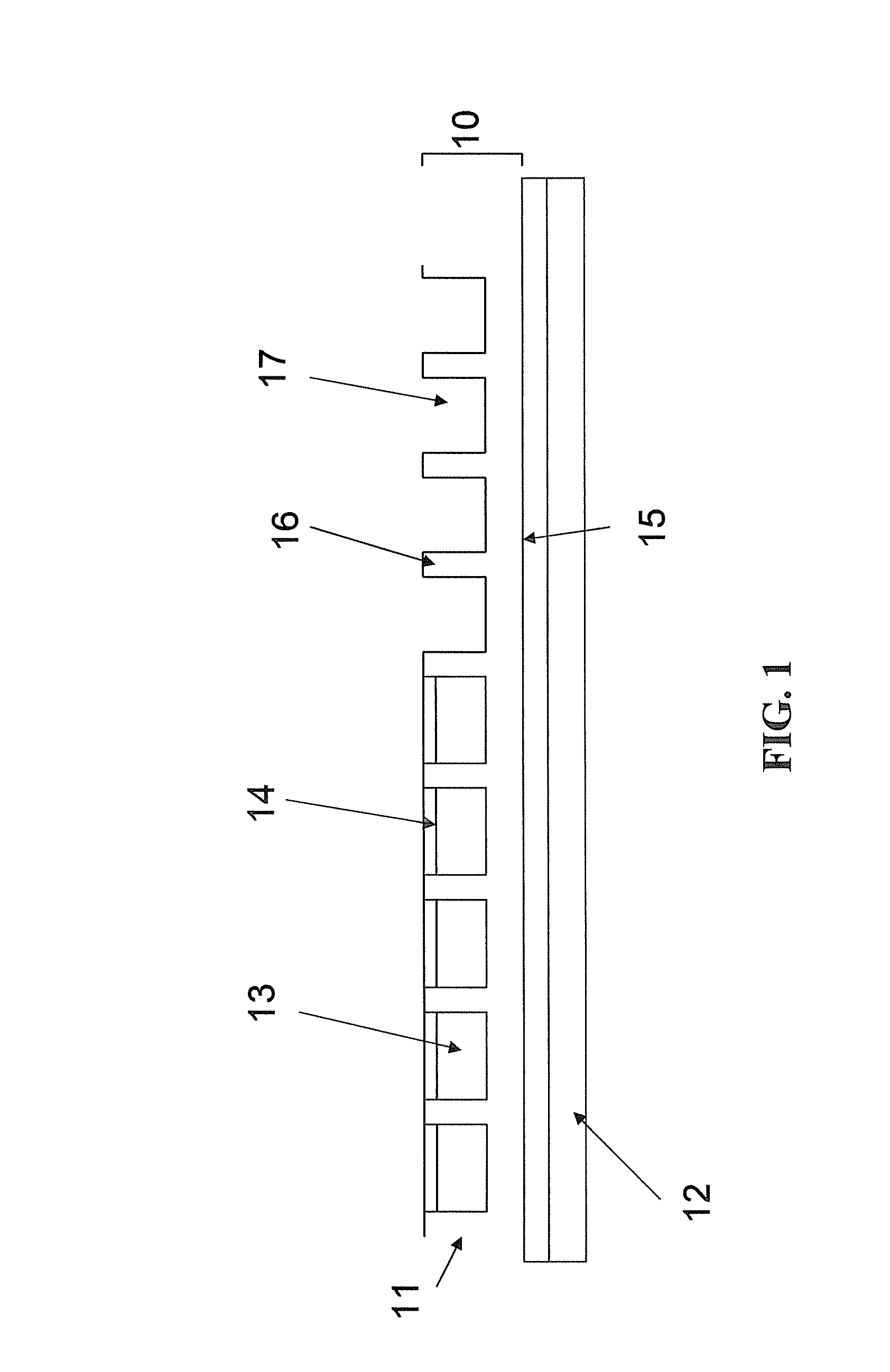
[0020]FIG. 1 illustrates the film structure (10) which comprises one or more microcups (11). The microcups comprise partition walls (16) and top openings (17). The film structure (10) may be formed on a substrate layer (12) which may optionally comprise an electrode layer (not shown). There may also be an optional primer layer (15) between the microcups and the substrate layer (12). The microcups are filled with a liquid composition (13) and top-sealed with a polymeric sealing layer (14).

[0021]1. Formation of the Microcups

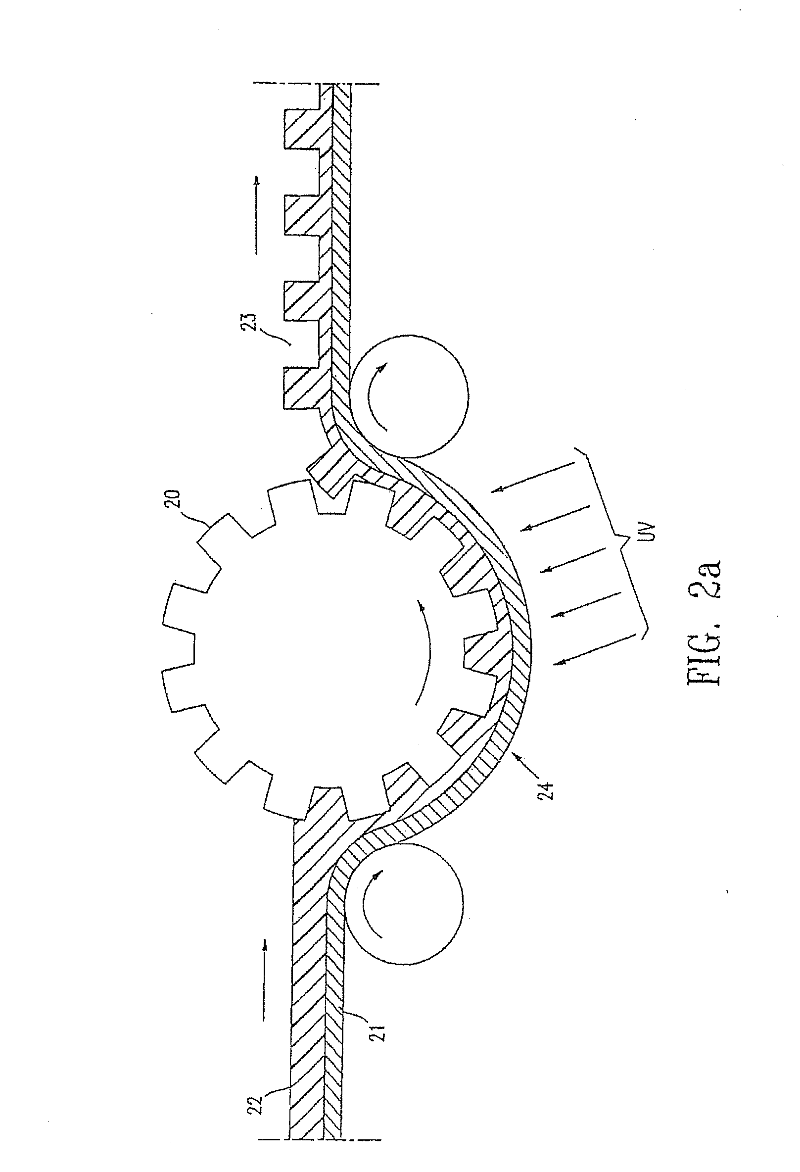
[0022](a) Microembossing

[0023]This processing step is shown in FIGS. 2a and 2b. A male mold (20) may be placed either above (FIG. 2a) or below (FIG. 2b) the web (24). The microcups may be formed on a flexible substrate layer (21). The substrate layer (21) may optionally comprise an electrode layer (not shown), which is suitable especially for display applications or other applications the operation of which involves the application of a voltage or ...


PUM

PropertyMeasurementUnit
Percent by massaaaaaaaaaa
Solubility (ppm)aaaaaaaaaa

Abstract

The present invention describes a film structure which comprises a plurality of microcups and the microcups are filled with a liquid composition and top-sealed with a sealing layer which is hardened in situ. The liquid composition may be a display fluid or a pharmaceutical composition. The present invention is directed to a liquid crystal display, a display device and a transdermal delivery system.

Description

[0001]This application claims the benefit of U.S. Provisional Application No. 60 / 831,779, filed Jul. 18, 2006, which is incorporated herein by reference in its entirety.DISCUSSION OF RELATED ART[0002]Various structures with peripheral plates or walls containing a liquid component were previously known. For example, a liquid component may be filled between two parallel or near-parallel surfaces and, in such a case, the liquid component is present in a continuous form. The two plates may be edge sealed first with fill holes for subsequent filling of the liquid component. Alternatively, the liquid component may be dropped on one of the two plates (before or after application of the edge sealing adhesive), followed by placing a second plate on top of the first plate to contain the liquid component between the two plates. In some cases, spacers may be present in the continuous liquid phase to control the distance between the two plates. However, such a continuous liquid phase structure s...

Claims


Application Information

Patent Timeline
IPC IPC(8): A61K8/02A61P17/00G02F1/1334
CPCA61K8/0295A61Q19/06C09K19/544A61K9/0014G02F1/133377G02F1/1341C09K2019/546A61P17/00A61N1/0448A61N1/303G02F1/1334
Inventor ZANG, HONGMEI
Owner SIPIX IMAGING INC
Features
  • Generate Ideas
  • Intellectual Property
  • Life Sciences
  • Materials
  • Tech Scout
  • Unparalleled Data Quality
  • Higher Quality Content
  • 60% Fewer Hallucinations
Learn More