Press for producing pressed parts from powdered material

Inactive Publication Date: 2008-01-24
FETTE
View PDF6 Cites 13 Cited by
  • Summary
  • Abstract
  • Description
  • Claims
  • Application Information

AI Technical Summary

Benefits of technology

[0017] The adjusting drive for the transversely movable part is, according to a further embodiment of the invention, preferably arranged on the die table. Finally, according to an embodiment of the invention, it

Problems solved by technology

Mole specifically, it is conceivable to predetermine this final position by end stops, but such stops are conventionally not used due to the speed of production and/or protection of the tools.
Different filling amounts, however, might have the result that the sinte

Method used


Image

  • Press for producing pressed parts from powdered material
  • Press for producing pressed parts from powdered material
  • Press for producing pressed parts from powdered material

Examples


Embodiment Construction

[0022] While this invention may be embodied in many different forms, there are described in detail herein a specific preferred embodiment of the invention. This description is an exemplification of the principles of the invention and is not intended to limit the invention to the particular embodiment illustrated

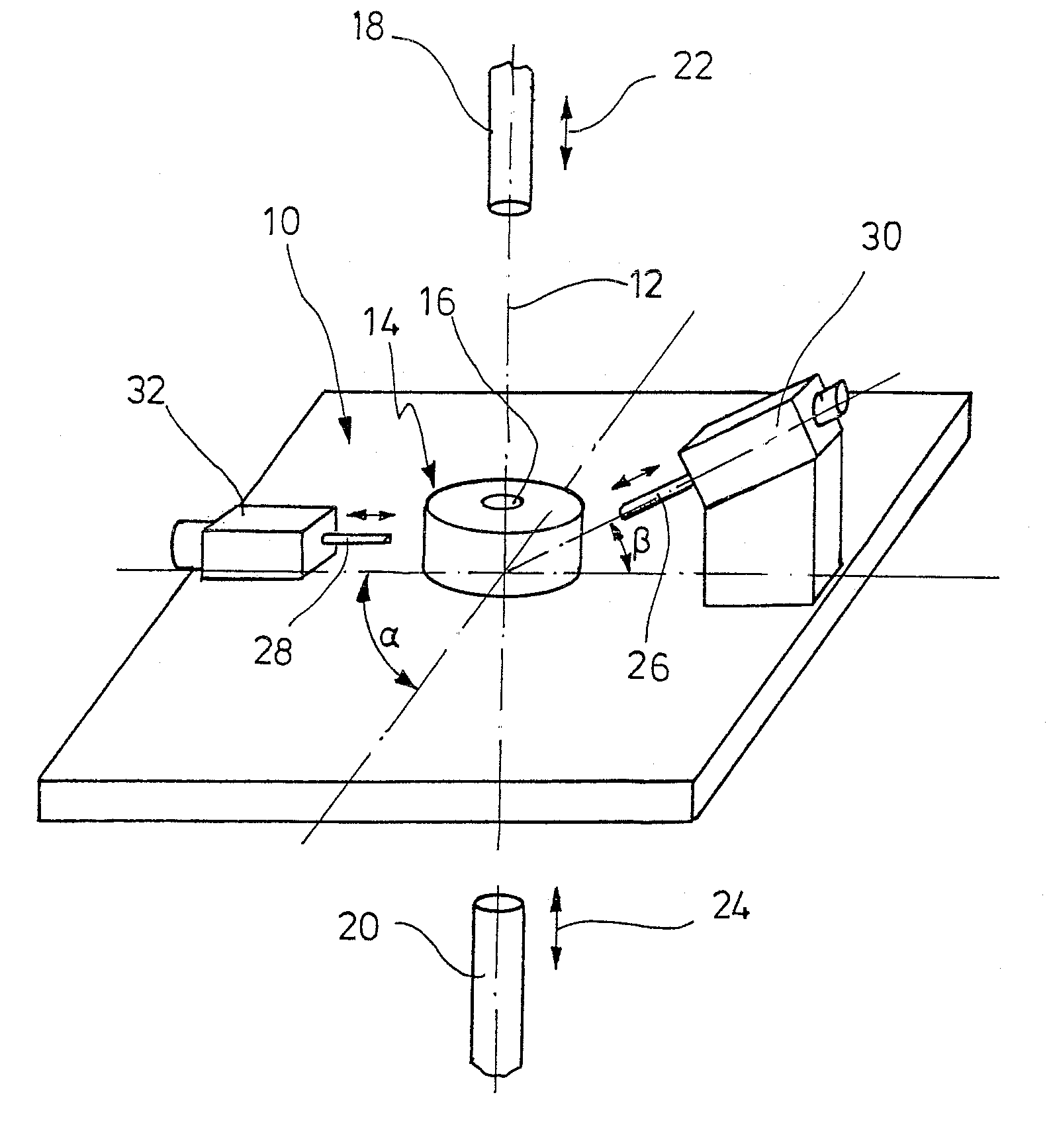
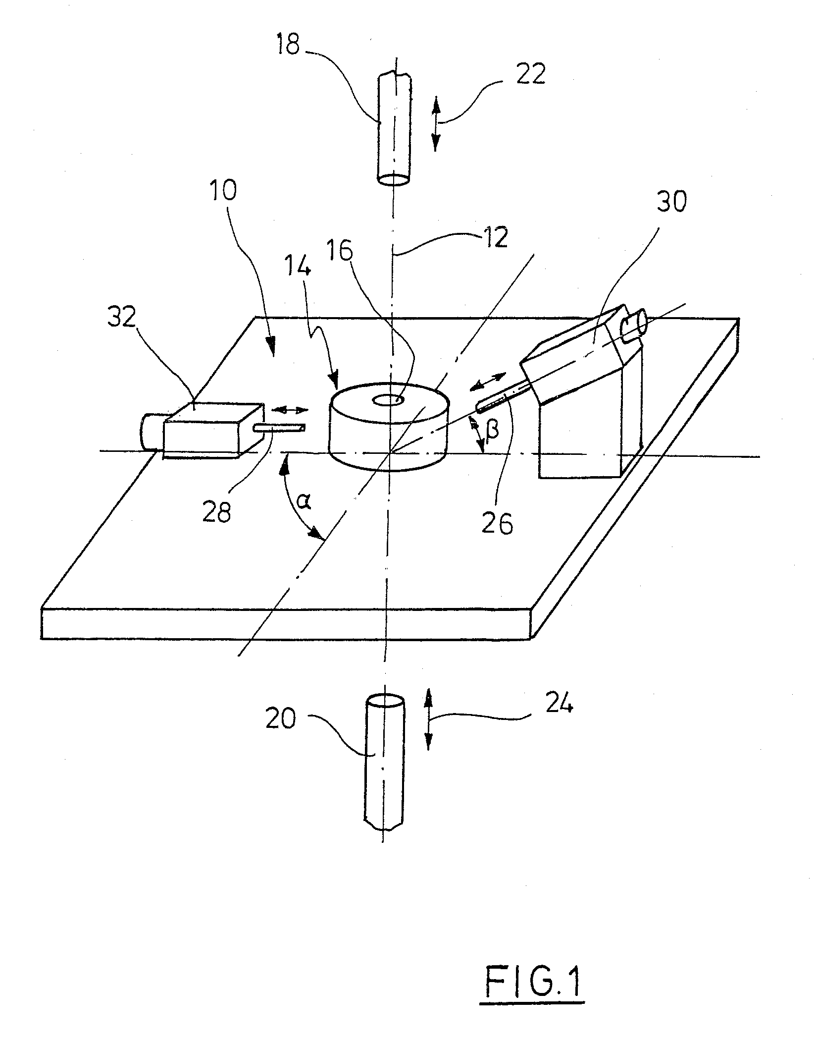
[0023] A die table 10, which may also be denoted as a die plate, is arranged in a flame of a press, not shown, for the production of powdered goods. The die table 10 may be arranged in a stationary manner in the press frame (ejection operation) or may in turn be displaced vertically along an axis 12 by hydraulic cylinders, not shown here (withdrawal method). A die 14 is fastened to the die table 10 with a mould cavity 16. An upper punch 18 and a lower punch 20 cooperate with the mould cavity. The upper and lower punch 18, 20 may be displaced by a hydraulic drive, not shown, along the axis 12, as indicated by the double arrow 22 and / or 24. When filling the mould cavity 16 wit...


PUM

PropertyMeasurementUnit
Timeaaaaaaaaaa
Forceaaaaaaaaaa
Magnetostrictionaaaaaaaaaa

Abstract

Press for producing pressed parts from powdered material with a die which may be clamped to a die table arranged in a press frame, in which a mould cavity is configured with a recess, and at least one upper and lower punch which cooperate with the mould cavity, the mould cavity being defined by at least one slider, transverse press punch or a movable part of the die, which may be displaced transversely to the vertical axis of the upper and lower punch (main pressing axis), and adjusting drives for the upper and lower punch and the slider and/or the displaceable die part attached in the press frame, characterised in that a sensor measures actual conditions of the adjusting drive for the slider, transverse press punch or the displaceable die part, the actual conditions being compared in a control device with a desired value and the control device actuating the adjusting drive for a slider, the transverse press punch or the displaceable die part via the energy supply to the adjusting drive according to the difference between the actual and desired condition.

Description

CROSS-REFERENCE TO RELATED APPLICATIONS [0001] Not applicable. STATEMENT REGARDING FEDERALLY SPONSORED RESEARCH [0002] Not applicable BACKGROUND OF THE INVENTION [0003] Such presses serve, for example, to produce pressed parts from metal powder for the subsequent sintering process, for example for the production of tools, such as cutting tools or the like. The powdered material is filled into the mould cavity of a die by means of a suitable filling device. The die is fastened onto a die plate or a die table and which, in turn, is arranged in a press frame. In the press frame, adjusting drives for at least one upper punch and at least one lower punch are also arranged which cooperate with the mould cavity and / or the powder therein. The axes of the adjusting drives are coaxial and vertical. A conventional drive provides, for example, hydraulic cylinders. [0004] In order to avoid subsequent finishing or at least to keep subsequent finishing to as low a level as possible, it is necessar...

Claims


Application Information

Patent Timeline
IPC IPC(8): B30B11/02
CPCB22F3/03B22F2003/031B22F2998/00B30B11/005B30B11/007B30B15/0094B30B11/02B22F5/10
Inventor PLUCINSKI, MARTINPANNEWITZ, THOMASBALTRUSCHAT, UDOJORDT, CARSTENGROTH, ANDREASTEETZEN, ANDREASROMER, HARALDNAEVE, JANMALLON, STEPHAN
Owner FETTE
Why Eureka
Try Eureka