Spine treatment devices and methods

a technology for spine disorders and treatment devices, applied in the field of spine treatment devices and methods, bone fixation devices, etc., can solve the problems of increased risk, uncertain outcome and efficacy of these treatments, and high risk of fusion procedures

Inactive Publication Date: 2008-01-24
DFINE INC
View PDF24 Cites 184 Cited by
  • Summary
  • Abstract
  • Description
  • Claims
  • Application Information

AI Technical Summary

Problems solved by technology

Many surgical and non-surgical treatments exist for patients with degenerative disc disease (DDD), but often the outcome and efficacy of these treatments are uncertain.
Fusion procedures are highly invasive procedure that carries surgical risk as well as the risk of transition syndrome described above wherein adjacent levels will be at increased risk for facet and discogenic pain.
While there have been significant advances in spinal fusion devices and surgical techniques, the procedure does not always work reliably.
Probably the most significant drawback of spinal fusion is termed the “transition syndrome” which describes the premature degeneration of discs at adjacent levels of the spine.
This is certainly the most vexing problem facing relatively young patients when considering spinal fusion surgery.
Repetitive or excessive trunkal motions, especially in rotation or extension, can irritate and injury facet joints or their encasing fibers.
Also, abnormal spinal biomechanics and bad posture can significantly increase stresses and thus accelerate wear and tear on the facet joints.
However, such disc replacement procedures are still highly invasive procedures, which require an anterior surgical approach through the abdomen.
Any disruption of the components that stabilized a vertebral segment (e.g., disc, facets, ligaments) decreases the clinical stability of the spine.

Method used


Image

  • Spine treatment devices and methods
  • Spine treatment devices and methods
  • Spine treatment devices and methods

Examples


Embodiment Construction

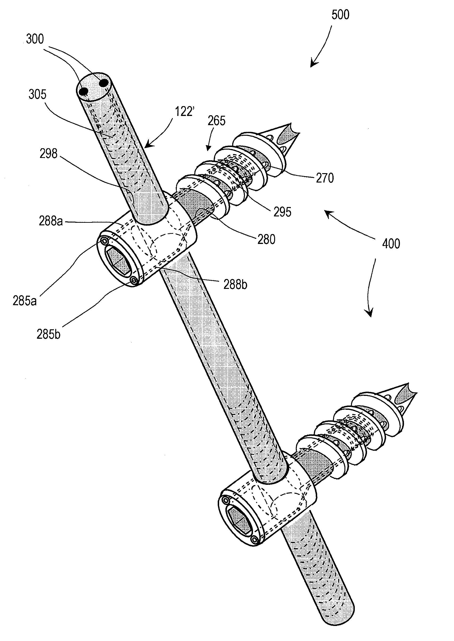
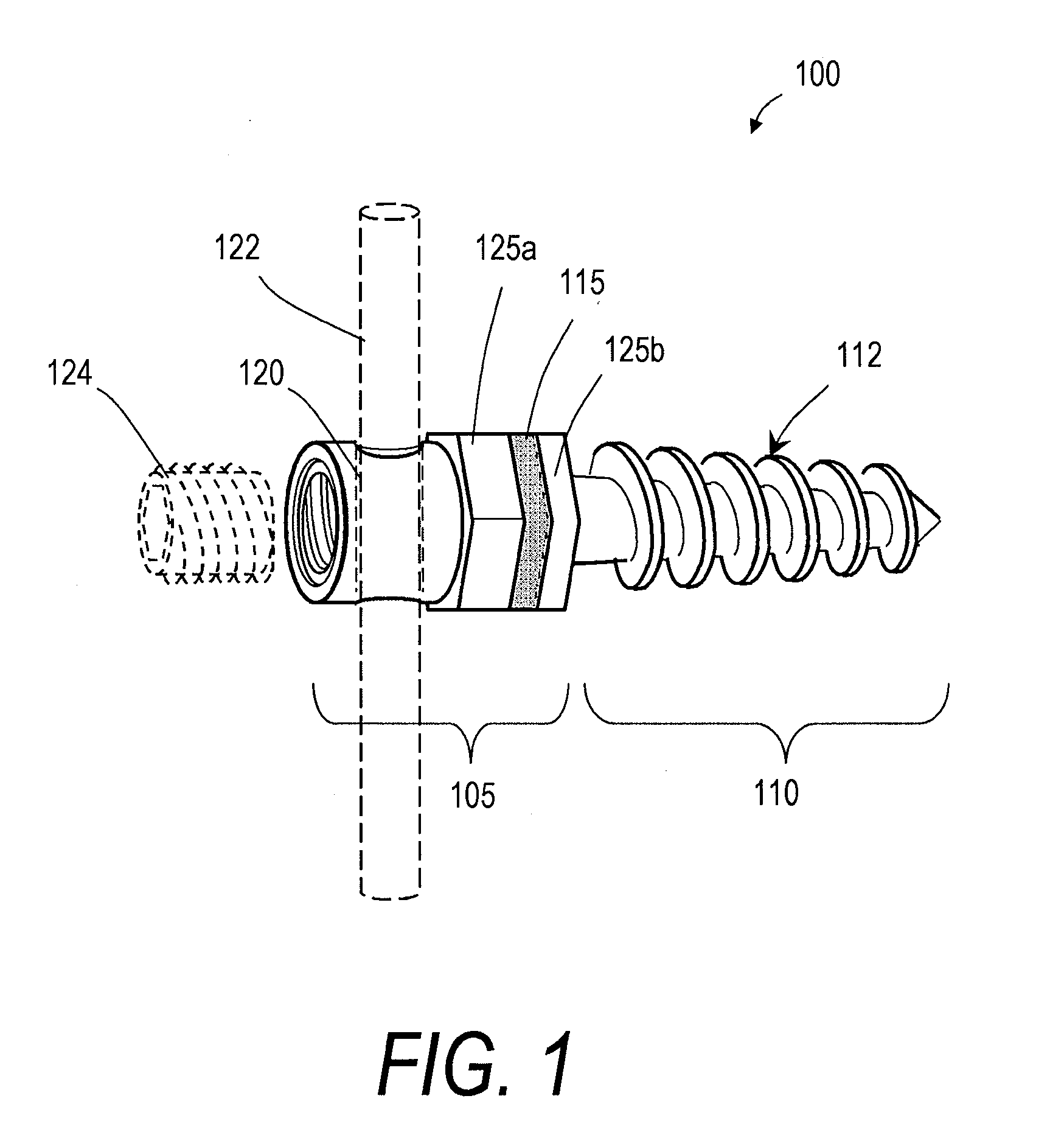
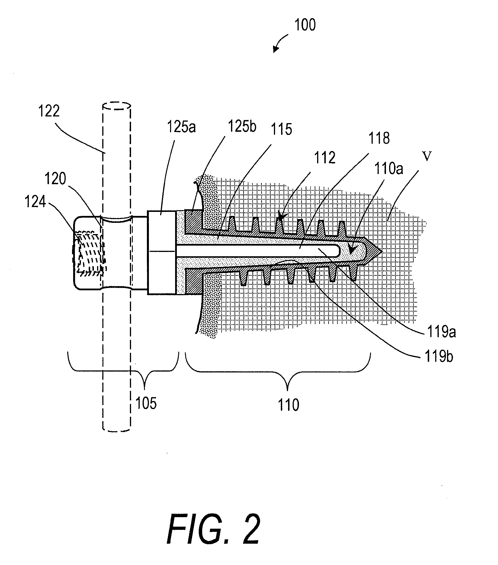
[0025]FIGS. 1 and 2 illustrate one embodiment of a bone fixation device 100 that can be used in a rod and pedicle screw system for spine stabilization, either fusion or dynamic. The device has a first end portion or head portion 105 and a second end portion or shaft portion 110 that can be introduced into a bore in a vertebra or bone V (see FIG. 2). In one embodiment, the single or multiple-flight threads 112 are preferably of a self-tapping type. As shown in FIG. 2, a resilient polymer member 115 can be disposed intermediate the head portion 105 and the shaft portion 110, and within a cavity 110a of the shaft portion 110. In the illustrated embodiment, the head portion 105 can be coupled to an elongated element 118 that extends axially within an elongated region of the resilient polymer member 115. A surface 119a of the elongated element 118 and a surface 119b of the shaft portion 110 can have any suitable texture or features for adherence to the polymer 115. The head portion 105 a...


PUM


Abstract

A spine implant device for fusion or dynamic stabilization of a spine segment can include a fixation device with a shaft portion for engaging bone and a proximal end for coupling to a rod that allows for limited flexing of the proximal end relative to the shaft portion. A spine implant system and method utilizing such a bone fixation device can include an energy delivery mechanism for on-demand curing of bone cement delivered through the bone fixation device into a bone.

Description

CROSS-REFERENCE TO RELATED APPLICATIONS [0001] This application claims the benefit of U.S. Provisional Patent Application No. 60 / 832,121 filed Jul. 21, 2006, and of U.S. Provisional Patent Application No. 60 / 831,925, filed Jul. 20, 2006, the entire contents of both of which are incorporated herein by reference and should be considered a part of this specification.BACKGROUND OF THE INVENTION [0002] 1. Field of the Invention [0003] The invention relates generally to implant systems and methods for treating a spine disorder, and more particularly relates to bone fixation devices and systems configured for fusion and dynamic stabilization systems for re-distributing loads within a spine segment while still allowing for flexion, extension, lateral bending and torsion. [0004] 2. Description of the Related Art [0005] Thoracic and lumbar spinal disorders and discogenic pain are major socio-economic concerns in the United States affecting over 70% of the population at some point in life. Low...

Claims


Application Information

Patent Timeline
Patent Type & Authority Applications(United States)
IPC IPC(8): A61B17/58A61B17/56
CPCA61B17/7002A61B17/864A61B2017/00867A61B17/8685A61B17/866
Inventor SHADDUCK, JOHN H.TRUCKAI, CSABALUZZI, ROBERT
Owner DFINE INC
Why Eureka
Try Eureka