Controller for electric power steering apparatus

Inactive Publication Date: 2008-01-24
NSK LTD
View PDF0 Cites 25 Cited by
  • Summary
  • Abstract
  • Description
  • Claims
  • Application Information

AI Technical Summary

Benefits of technology

[0018] In view of the above, one object of the present invention is to provide a controller for an electric power steering apparat

Problems solved by technology

However, as mentioned previously, when the deviation of the actual yaw rate from the standard yaw rate is used as a value equivalent to the grip status, the deviation of the yaw rate represents the grip status, but a comparatively large error exists between the grip status represented by the deviation and an actual grip status.
Moreover, since the standard yaw rate uses a characteristic achieved in a steady traveling state, difficulty is encountered in acquiring an unerring grip status when dynamic transient response; specifically, quick steering, has been performed.
Further, since the yaw rate is susceptible to the inertia of the vehicle, and the like, response of the yaw rate is slow.
For this reason, even in this case, difficulty is encountered in acquiring an unerring grip status when, specifically, quick steering has been performed.
Therefore, when the grip status has been estimated by use of the deviation of the yaw rate as mentioned above and when

Method used


Image

  • Controller for electric power steering apparatus
  • Controller for electric power steering apparatus
  • Controller for electric power steering apparatus

Examples


first embodiment

[0108] To begin with, a first embodiment will be described.

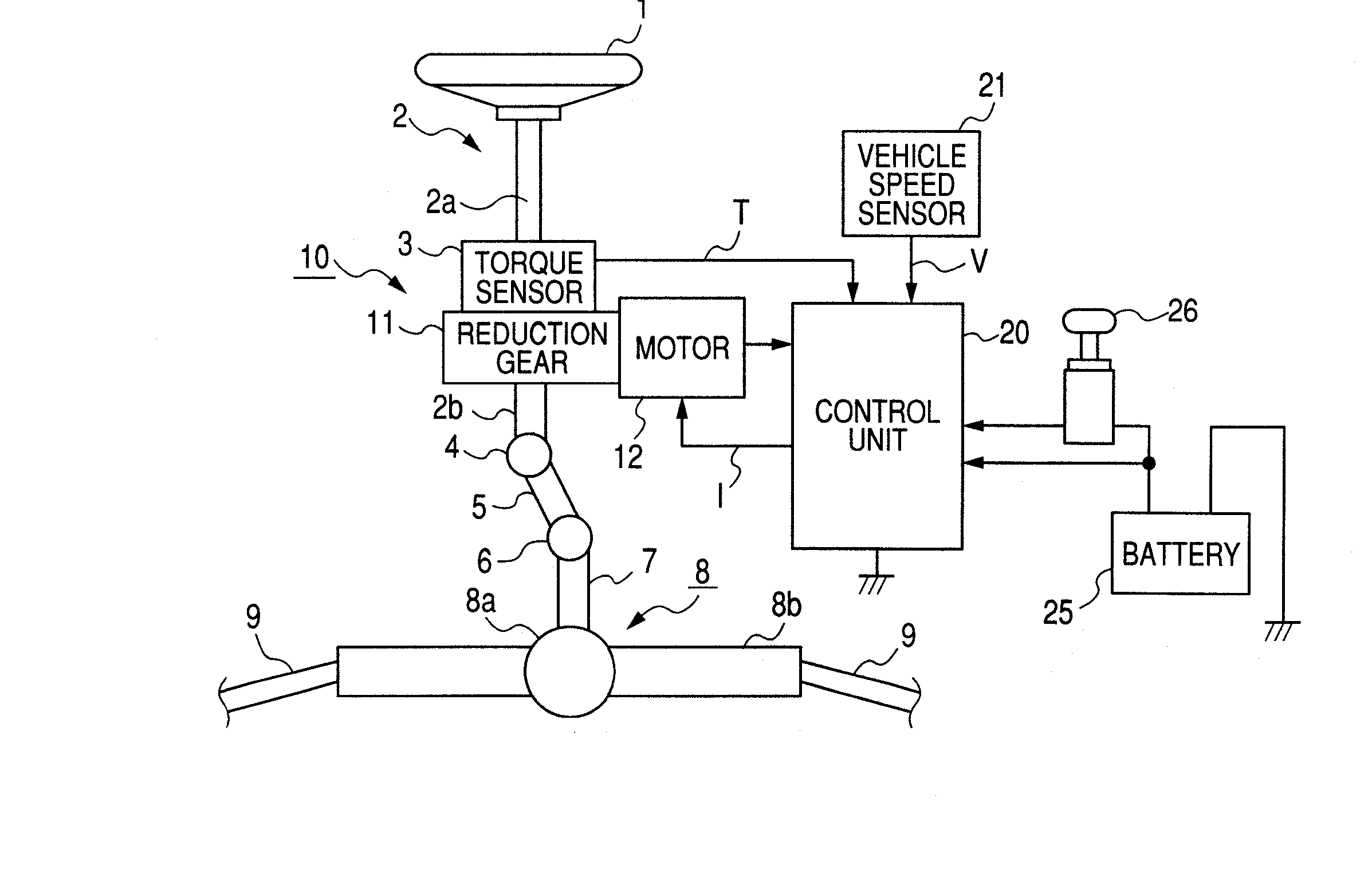
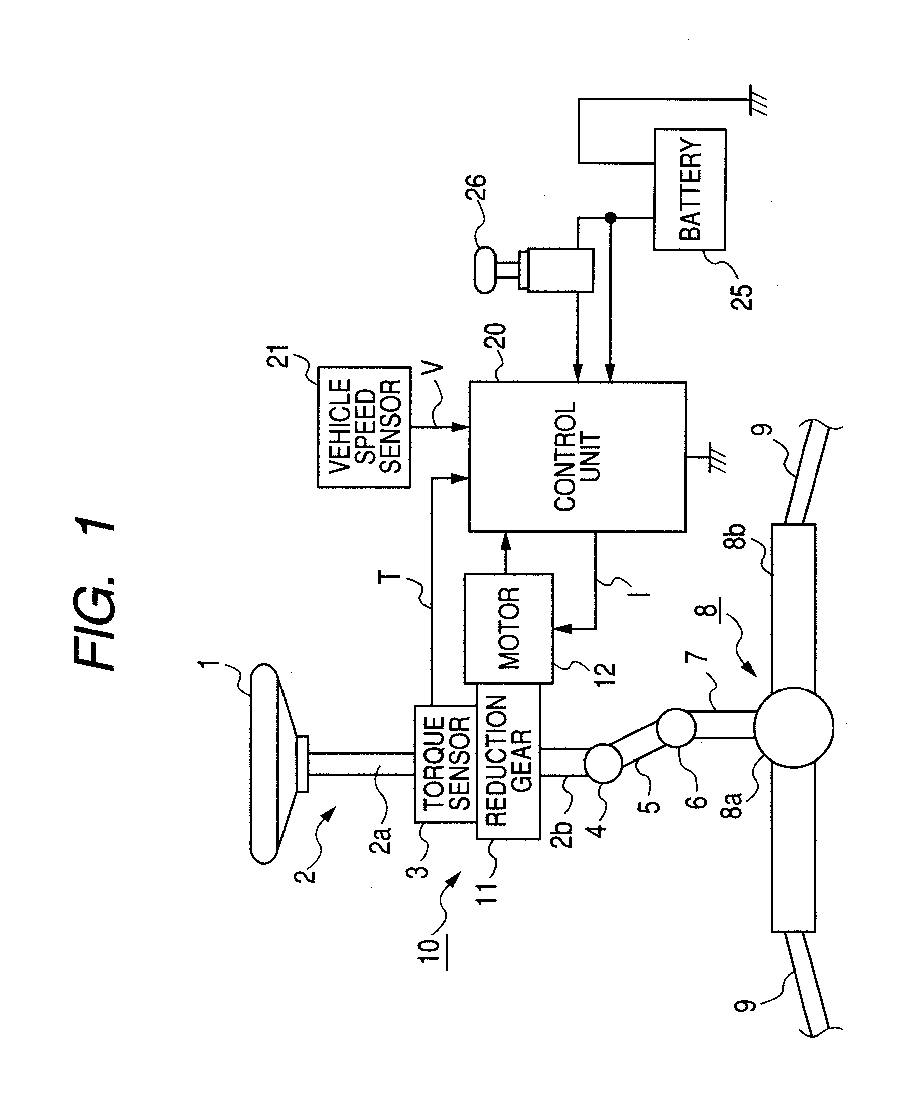
[0109]FIG. 1 is a block diagram of the entirety showing the first embodiment of the present invention.

[0110] In the drawing, reference numeral 1 designates a steering wheel. Steering force exerted on the steering wheel 1 by a driver is transmitted to a steering shaft 2 having an input shaft 2a and an output shaft 2b. In the steering shaft 2, one end of the input shaft 2s is coupled to the steering wheel 1, and the other end of the same is coupled to one end of the output shaft 2b by way of a torque sensor 3 which senses steering torque.

[0111] The steering force transmitted to the output shaft 2b is transmitted to a lower shaft 5 by way of a universal joint 4, and further to a pinion shaft 7 by way of a universal joint 6. The steering force transmitted to this pinion shaft 7 is transmitted to tie rods 9 by way of a steering gear 8, thereby steering unillustrated wheels. The steering gear 8 is formed into a rack-and-pinion ...

second embodiment

[0151] A second embodiment of the present invention will now be described.

[0152] The second embodiment is analogous to the first embodiment, except for the configuration of the control unit 20 being different, and hence the same reference numerals are assigned to the same sections, and their detailed explanations are omitted.

[0153]FIG. 9 is a block diagram showing the schematic configuration of the control unit 20 of the second embodiment.

[0154] In the control unit 20 of the second embodiment, the current command value Itv computed by the command value computing section 40 is input to the multiplication section 56, where the current command value is multiplied by a correction coefficient K to be described later, to thus compute a corrected current command value Itv′. This corrected current command value Itv′ is input to the addition section 60A. The addition section 60B adds the convergence control signal CM2 computed by the convergence control section 44 to the inertia compensat...

third embodiment

[0169] A third embodiment of the present invention will now be described.

[0170] This third embodiment is identical with the first embodiment except that the third embodiment is provided with a turning further / returning operation determination section (steering direction determination unit) 57 and a gain section 58 for multiplying a gain responsive to a result of determination rendered by the turning further / returning operation determination section 57. Hence, like sections are assigned like reference numerals, and their detailed explanations are omitted.

[0171]FIG. 11 is a block diagram showing the general configuration of the control unit 20 of the third embodiment

[0172] In the control unit 20 of the third embodiment, that torque correction value ΔTg responsive to the grip loss level “g” computed by the torque correction value computing section 51 is input to the multiplication section 52, where the torque correction value is multiplied by the absolute value of the angular speed ...


PUM


Abstract

A computed SAT value SATa is computed, and an estimated SAT value SATb is estimated from lateral force. A grip loss level “g” is computed from difference between the computed self aligning torque value SATA and the estimated SAT value SATb. Torque correction value ΔT which becomes greater with an increase in grip loss level “g” and an increase in angular speed ω is set in accordance with the grip loss level “g” and the angular speed ω of an electric motor 12 serving as corresponding steering angular speed. The corresponding torque correction value ΔT is subtracted from the current command value Itv responsive to the steering torque T and the vehicle speed V, thereby correcting the current command value Itv. The thus-corrected current command value Itv is taken as a steering assist command value Im, and the electric motor 12 is driven based on the steering assist command value.

Description

BACKGROUND OF THE INVENTION [0001] 1. Field of the Invention [0002] The present invention relates to a controller for an electric power steering apparatus which imparts steering assist force to a steering mechanism of a vehicle by a motor, and particularly to a controller for an electric power steering apparatus capable of stabilizing the behavior of a vehicle even when grips of tires have been lost. [0003] 2. Description of Related Art [0004] An electric power steering system—where a motor is driven in response to steering torque generated as a result of a driver operating a steering wheel, to thus impart steering assist power to a steering mechanism—has hitherto become prevalent as a steering system. [0005] Moreover, in relation to such an electric power steering system, there have also been proposed an electric power steering system which determines self aligning torque—which acts so as to return wheels attached to a vehicle to neutral positions—and uses the thus-determined torqu...

Claims


Application Information

Patent Timeline
IPC IPC(8): B62D5/04B62D1/16
CPCB62D6/008B62D5/0463
Inventor ENDO, SHUJIAOKI, YUHOREUNGWETWATTANA, APIWAT
Owner NSK LTD
Why Eureka
Try Eureka