Thermal storage unit for air conditioning applications

a technology of storage unit and air conditioning system, which is applied in the field of air conditioning system, can solve the problems of not being able to meet the needs of the user, and achieve the effect of solving the problem of not being able to meet the needs of the user

Active Publication Date: 2008-01-31
JACOBI ROBERT W
View PDF10 Cites 35 Cited by
  • Summary
  • Abstract
  • Description
  • Claims
  • Application Information

AI Technical Summary

Problems solved by technology

Even though this may be a monumental task with numerous issues, it is nonetheless a continuing problem, especially in densely populated, high ambient temperature locations such as southern California.

Method used


Image

  • Thermal storage unit for air conditioning applications
  • Thermal storage unit for air conditioning applications
  • Thermal storage unit for air conditioning applications

Examples


Embodiment Construction

[0011]For the purposes of promoting an understanding of the principles of the invention, reference will now be made to the embodiments illustrated in the drawings and specific language will be used to describe the same. It will nevertheless be understood that no limitation of the scope of the invention is thereby intended, such alterations and further modifications in the illustrated device, and such further applications of the principles of the invention as illustrated therein being contemplated as would normally occur to one skilled in the art to which the invention relates.

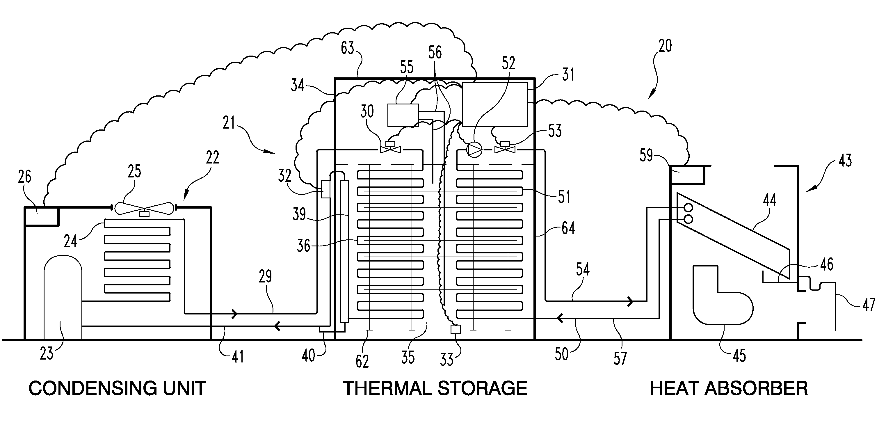
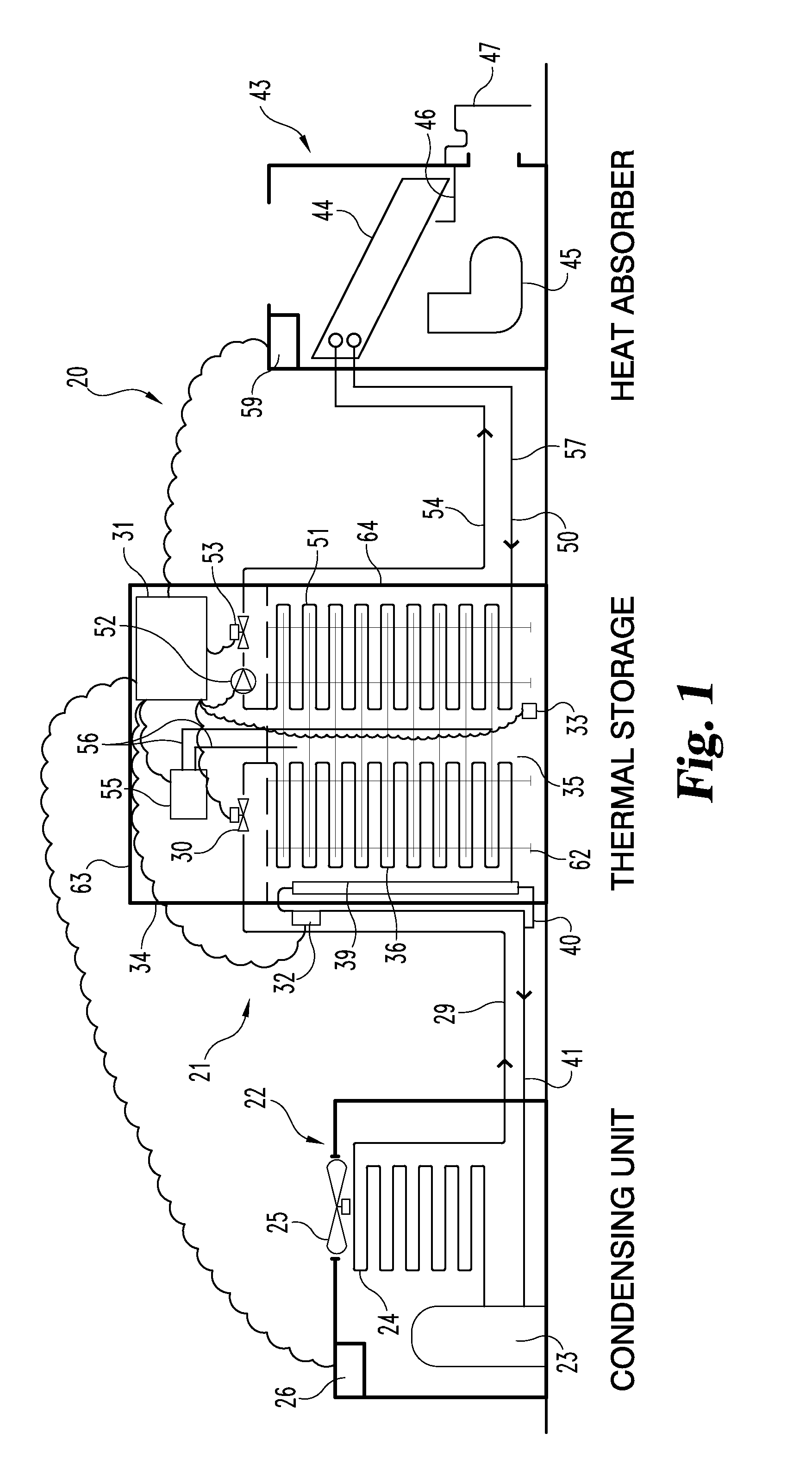
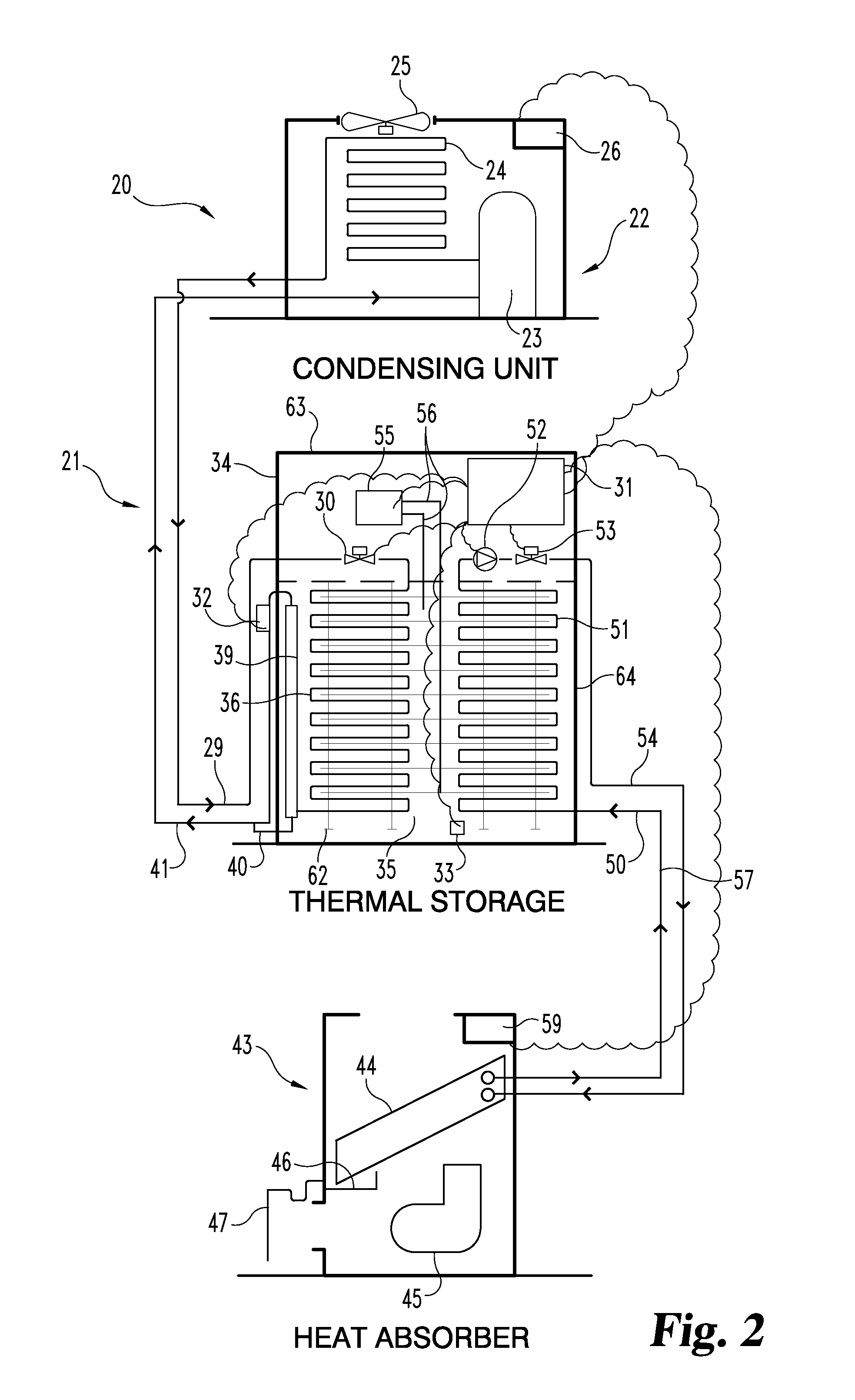
[0012]Referring to FIG. 1, there is illustrated in schematic form an air conditioning system 20 that includes a cold storage subassembly 21. Since the focus of the present invention is directed to this cold storage subassembly 21, we are using herein the phrase “thermal energy storage” as a descriptive phrase for system 20. In brief, this thermal energy storage system 20 operates the high energy consuming compr...


PUM


Abstract

Disclosed is a demand shifting thermal storage system employing a heat transfer/thermal energy storage vessel to produce and hold a phase change fluid using an air cooled/water cooled/ground coupled or evaporative condensing unit to generate the cold fluid with a separate and dependent circuit coupled to the indoor cooling load to remove heat from the HVAC or process cooling load using one or multiple indoor coils to absorb heat returning the heat to the thermal energy storage vessel to reject the space heat, cool the space and continue the cycle.

Description

[0001]The present application is a Continuation-In-Part (CIP) of, and claims the benefit of, U.S. Provisional Patent Application Ser. No. 60 / 833,514, filed Jul. 26, 2006, entitled “Thermal Storage Unit For Air Conditioning Applications” which is hereby incorporated by reference in its entirety.BACKGROUND OF THE INVENTION[0002]The present invention relates in general to an air conditioning system for cooling an interior space of a structure. More specifically, the present invention relates to an air conditioning system that includes a thermal storage subassembly that can be positioned interior or exterior to the structure. In one embodiment of the present invention, the thermal storage subassembly includes a storage tank with a cold storage fluid and a pair of heat exchange coils. One coil is connected to a condensing unit as part of a refrigerant circuit for cooling of the cold storage fluid. The other coil is connected to a heat absorption coil as part of a second, separate fluid c...

Claims


Application Information

Patent Timeline
Patent Type & Authority Applications(United States)
IPC IPC(8): F25D17/02F28D20/00
CPCF24F5/0017Y02E60/147Y02E60/145F28D20/021Y02E60/14
Inventor JACOBI, ROBERT W.
Owner JACOBI ROBERT W
Why Eureka
Try Eureka