Conical involute gear and gear pair

a technology of involute gears and gear pairs, which is applied in the direction of gearing elements, belts/chains/gearrings, hoisting equipments, etc., can solve the problems of difficult to form the involute tooth profile, difficult to achieve a suitable engagement function, and difficult to smoothly engage the gears, etc., to achieve a wide conical angle and facilitate manufacturing

Active Publication Date: 2008-01-31
JTEKT CORP
View PDF8 Cites 23 Cited by
  • Summary
  • Abstract
  • Description
  • Claims
  • Application Information

AI Technical Summary

Benefits of technology

[0009]An objective of the present invention is to provide a conical involute gear that precisely engages, is easily manufactured, and

Problems solved by technology

Further, since a gear generating process is not employed, it is hard to form the involute tooth profile.
Accordingly, it is impossible to smoothly engage the gears, and it is impossible to achieve a suitable engaging function as the involute gear.
Therefore, the engagement between both the gears 311 and 321 i

Method used


Image

  • Conical involute gear and gear pair
  • Conical involute gear and gear pair
  • Conical involute gear and gear pair

Examples


Embodiment Construction

[0028]A description will be given of one embodiment of the present invention with reference to FIG. 1(A) and FIGS. 2 to 9.

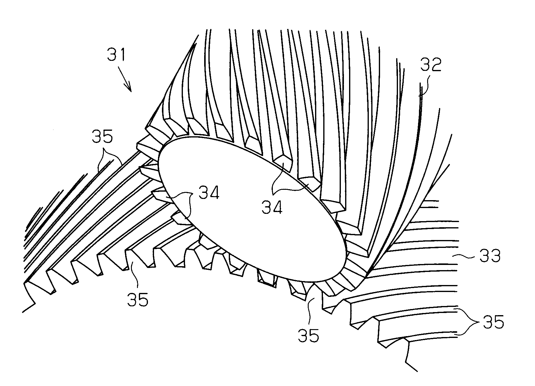
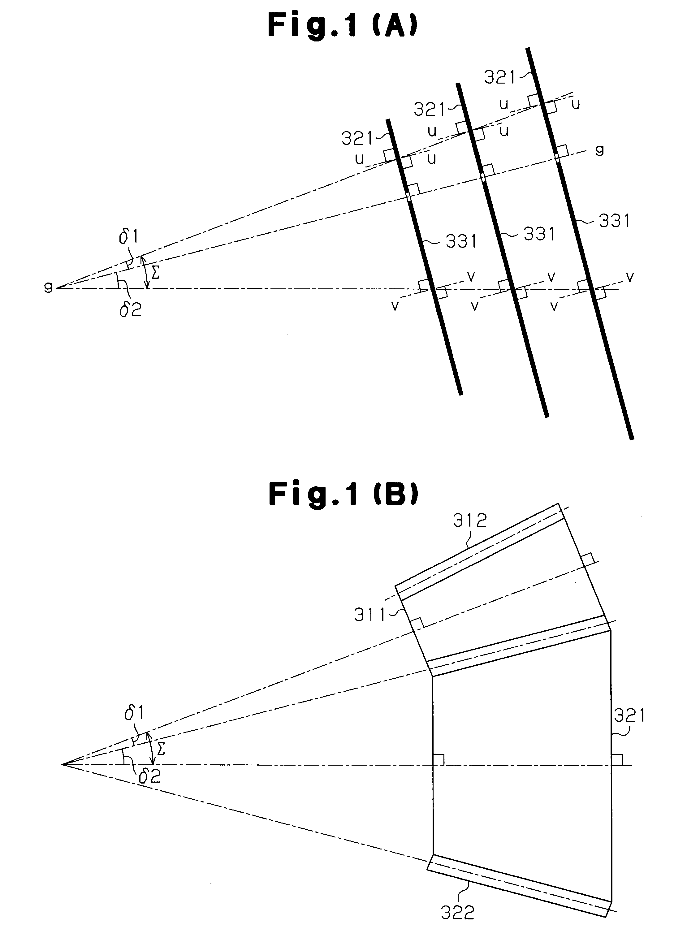
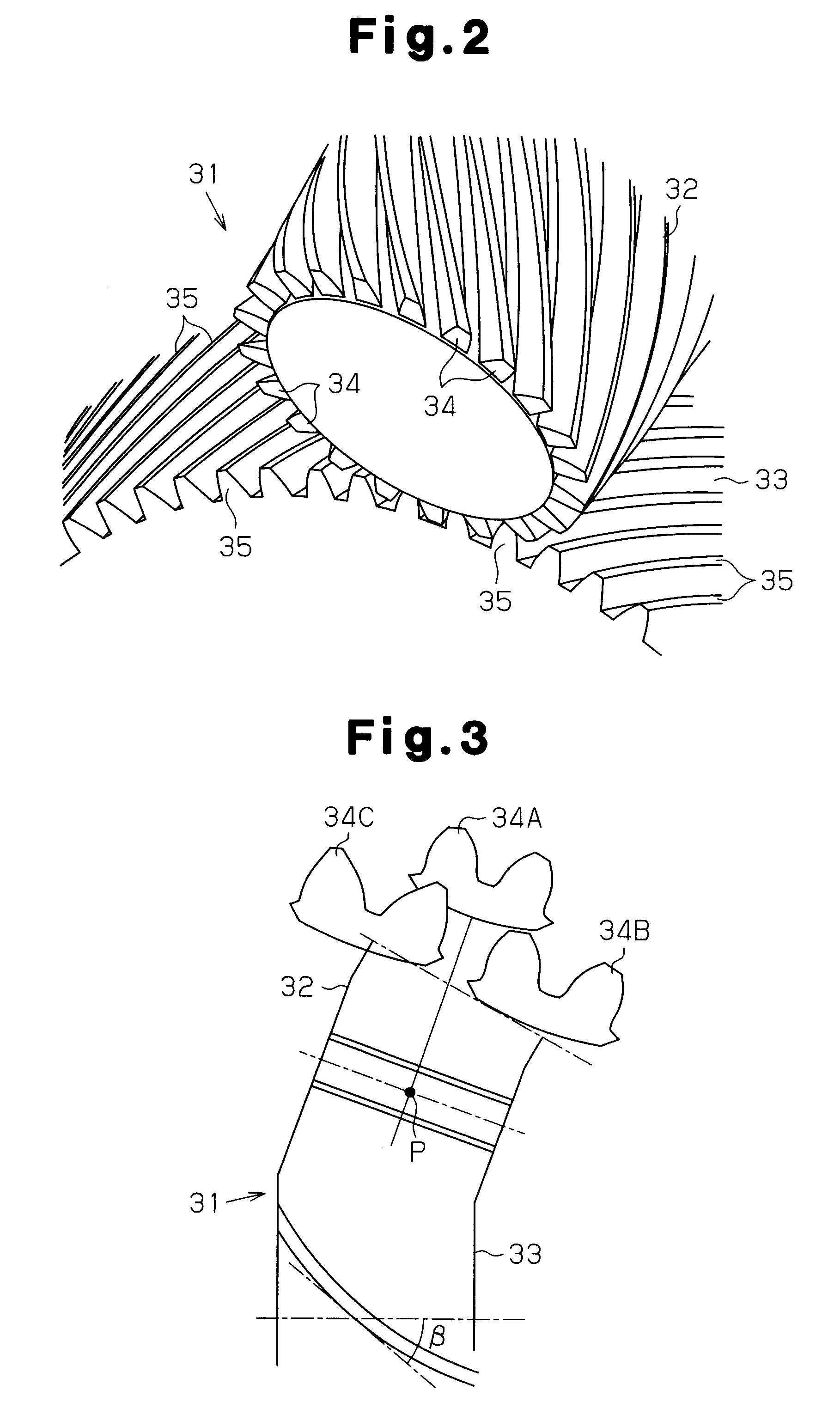
[0029]As shown in FIGS. 2, 3 and 6, a gear pair 31 is constituted by a small-diameter conical involute gear (hereinafter, referred to as a small-diameter conical gear) 32, and a large-diameter conical involute gear (hereinafter, referred to as a large-diameter conical gear) 33. The gears 32 and 33 are engaged with each other, and have predetermined conical angles δ1 and δ2, respectively. The conical gear 32 has a set of teeth 34, of the number of teeth z1, and the conical gear 33 has a set of teeth 35, of the number of teeth z2. The teeth 34 and 35 have an involute tooth profile and are constituted by helical teeth having a spiral angle β.

[0030]An addendum modification coefficient of each of the teeth 34 and 35 is non-linearly changed in each of a face width direction. In other words, as shown in FIGS. 3, 6 and 7, the addendum modification coefficient (an addendu...


PUM


Abstract

A gear pair includes a small-diameter conical involute gear having a conical angle, and a large-diameter conical involute gear having a conical angle. The small-diameter conical involute gear and the large-diameter conical involute gear are constituted by an aggregate of imaginary cylindrical gears.

Description

BACKGROUND OF THE INVENTION[0001]The present invention relates to a conical gear having an involute tooth profile and a gear pair in which the conical gears are engaged.[0002]In general, a bevel gear is used for engaging a plurality of gears which respectively rotate around a plurality of intersecting axes. In order to smoothly transmit rotation by the bevel gear, there are frequently used spiral bevel gears 103 and 104 having circular arc shaped teeth 101 and 102 and formed in a pseudo-spiral shape, as shown in FIG. 10(A).[0003]In the manufacture of the bevel gears 103 and 104 mentioned above, the teeth 101 and 102 are machined one by one by a milling tool 107 in which a plurality of cutting chips 106 are arranged in an outer circumferential portion of a disc 105, as shown in FIG. 10(B). Accordingly, the working time is elongated and the working efficiency is lowered. Further, since a gear generating process is not employed, it is hard to form the involute tooth profile. Accordingl...

Claims


Application Information

Patent Timeline
IPC IPC(8): F16H55/00F16H57/08
CPCF16H55/0813Y10T74/19972Y10T74/19963Y10T74/19958
Inventor KOBAYASHI, TSUNE
Owner JTEKT CORP
Why Eureka
Try Eureka