Transparent digitiser

a technology of transparent digitiser and transparent foil, which is applied in the field of transparent digitiser, can solve the problems of limiting the mobility of the digitiser, the inability to use transparent conductive foil, and the inability to use wacom's method with standard metallic conductors, etc., and achieves the effect of free of nois

Active Publication Date: 2008-01-31
MICROSOFT TECH LICENSING LLC
View PDF37 Cites 115 Cited by
  • Summary
  • Abstract
  • Description
  • Claims
  • Application Information

AI Technical Summary

Benefits of technology

[0014] It is a further object of the present invention to enable effective usage of a transparent foil sensor mounted on top of a Flat Panel Display (FPD) such as an LCD or an OLED panel in order to overcome the disadvantages emanating from use of a non-transparent sensor.
[0053] Preferably, the object produces an exponentially decaying signal, the digitizer further comprising signal multiplication functionality for multiplying the decaying signal by an opposite, exponentially rising signal, thereby to cancel out frequency side lobes and to increase frequency resolution of the digitizer.

Problems solved by technology

These new devices are usually not connected to standard keyboards, mice or like input devices, which are deemed to limit their mobility.
As such, Wacom's method has to use loops made of standard metallic conductors and cannot be used with transparent conductive foils, since the resistance of a conductive transparent line is very high.
Using high resistance conductive loops to energize the stylus requires a particularly high voltage input, in excess of 1 KV, which makes this solution impractical.
Without the use of transparent conductive material, however, the solution of Wacom merely succeeds in making the display difficult to view.
As such, integration of a non-transparent sensor into a FPD device is a very complicated and expensive process.
Due to the relatively long distance from the sensor, non-transparent sensors suffer from parallax, leading to inaccurate positioning of the stylus.
Positioning is especially inaccurate, that is parallax effects are especially large, when the stylus is held at an angle to the display.
Furthermore, again due to the relatively long distance from the sensor, back-mounted sensors suffer from inaccurate positioning of the stylus when the stylus is held close to the edge of the sensor.
In summary, due to the relatively long distance from the sensor, and furthermore due to the number of electronically active components likely to be located between the sensor and the stylus, back-mounted sensors may not achieve reliable positioning resolution.
However, an active, battery powered stylus is generally not regarded as a satisfactory solution for a number of reasons.
For example, an active stylus requires continuous maintenance and may even stop working and thereby render the entire computer device inoperable.
Also the active stylus requires recharging, and is more expensive than a passive device.
Therefore, an active stylus is currently unacceptable for the mobile consumer market.
A problem however, is that detection, which is based on electric fields, is carried out on the surface of an electronic display screen, and the screen surface is a relatively high noise environment in terms of electromagnetic activity.
The high noise environment necessarily reduces the resolution level of the digitizer.

Method used


Image

  • Transparent digitiser
  • Transparent digitiser
  • Transparent digitiser

Examples


Embodiment Construction

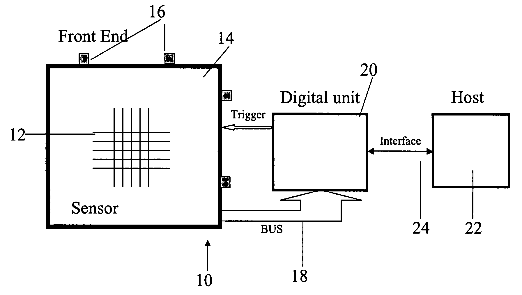
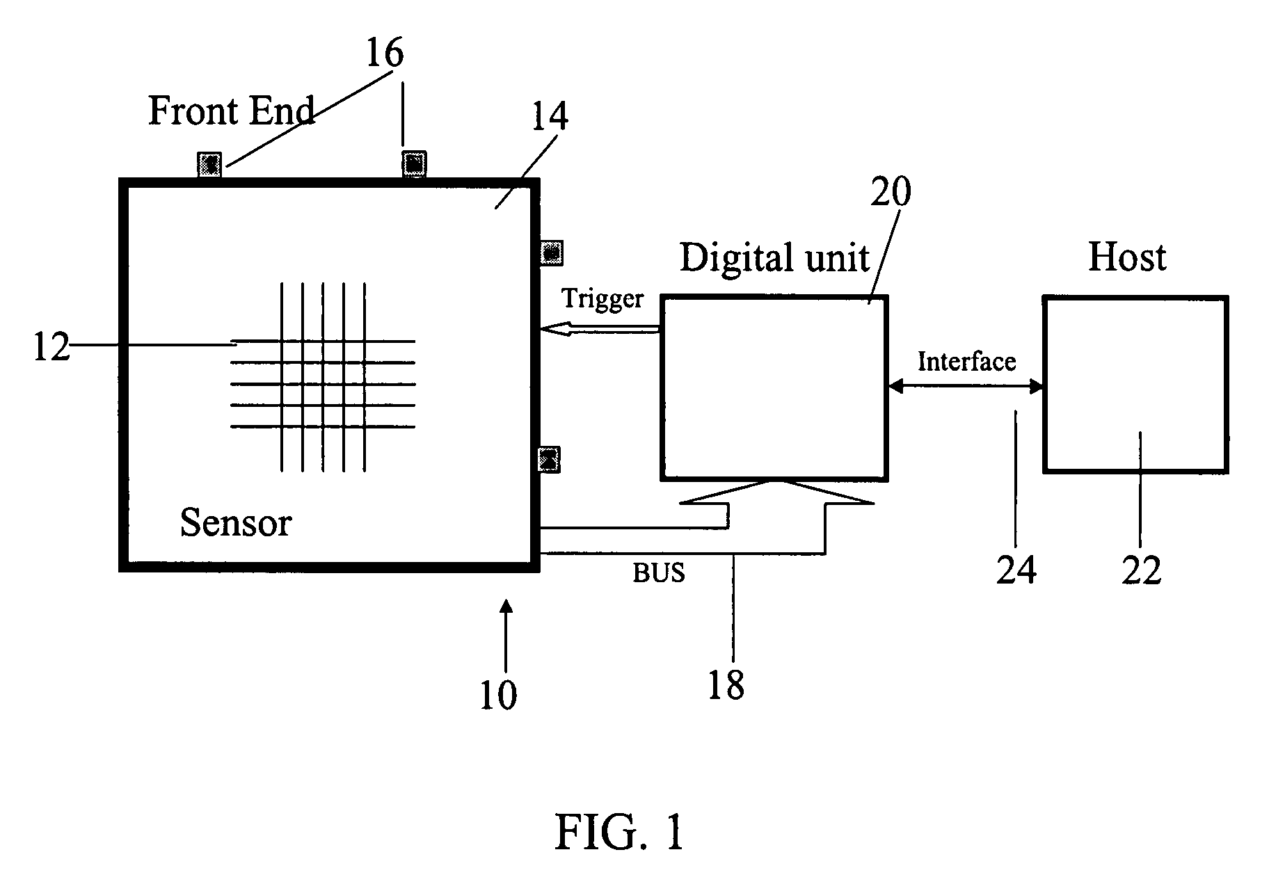
[0117] The present embodiments disclose a method and apparatus for locating and identifying physical objects, such as a stylus or game tokens, on top of a Flat Panel Display. The location of the physical objects is sensed by an electro magnetic transparent digitizer, which is preferably mounted on top of the display. The physical objects are preferably passive elements, that is they do not include any kind of internal power source. The passive elements are energized by a non-transparent excitation coil, which is placed substantially about the transparent sensor. The transparent sensor comprises a sensing grid or an arrangement of sensing loops, whose outputs are connected to sensing amplifiers. In one preferred embodiment the sensing amplifiers are differential amplifiers and in one preferred embodiment each sensing amplifier is connected to at least two non-adjacent outputs from the grid.

[0118] A further preferred embodiment comprises an arrangement of the passive stylus in which ...


PUM


Abstract

A digitizer for user interaction via an object with an electronically refreshable display screen, the digitizer comprising: a transparent sensing arrangement of detectors located at said electronically refreshable display screen for detecting an electric field of said object, said detectors having outputs, and an arrangement of differential amplifiers associated with said outputs, thereby to apply differential detection between said outputs.

Description

RELATIONSHIP TO EXISTING APPLICATIONS [0001] The present application is a divisional of U.S. patent application Ser. No. 10 / 649,708 filed Aug. 28, 2003, which claims the benefit of priority from U.S. Provisional Patent Application No. 60 / 406,662 filed Aug. 29, 2002, the contents of which are both incorporated herein by reference.FIELD AND BACKGROUND OF THE INVENTION [0002] The present invention relates to a transparent digitizer and, more particularly, but not exclusively to a transparent digitizer with a cordless stylus or like input device. [0003] U.S. patent application Ser. No. 09 / 628,334 “Physical Object Location Apparatus and Method and a Platform using the same” to Gamalong Ltd, the contents of which are hereby incorporated by reference, describes an electromagnetic method for locating physical objects on a flat screen display, that is to say a digitizer that can be incorporated into the active display screen of an electronic device. The present disclosure concerns further te...

Claims


Application Information

Patent Timeline
Patent Type & Authority Applications(United States)
IPC IPC(8): G06F3/033G06F3/046G06F3/041G09G5/00
CPCG06F3/03545G06F3/046G06F3/0418G06F3/0412G06F3/04162G06F3/038G06F2203/04804
Inventor MORAG, MEIRPERSKI, HAIM
Owner MICROSOFT TECH LICENSING LLC
Why Eureka
Try Eureka