Metal gasket

Inactive Publication Date: 2008-01-31
KOKUSAN BUHIN INDS
View PDF2 Cites 25 Cited by
  • Summary
  • Abstract
  • Description
  • Claims
  • Application Information

AI Technical Summary

Benefits of technology

[0022] A coating layer may be formed on the gasket component sheet at an area containing the bore bead. Forming this coating layer preferably further improves sealing performance.
[0023] In a preferred embodiment, a thick portion is formed on the shim sheet or a corresponding section of the gasket component sheet so as to be separated from the bolt insertion hole of the head bolt. Since a surface pressure around the combustion chamber between the cylinder block and cylinder head and the metal gasket increases as being closer to the head bolt, the formation of a thick portion at a position distant from the bolt insertion hole through which the head bolt is inserted, allows a uniform surface pressure to be provided all around the combustion chamber, thereby preferably improving sealing performance.
[0024] According to a metal gasket related to the present invention, a shim sheet is arranged on the outer periphery of a bore bead and thus serves as a stopper for preventing the bore beads from fully bending, which effectively blocks a deterioration in sealing performa

Problems solved by technology

Forming the stopper around the inner periphery of the bore bead in this way prevents permanent setting of the bore bead due to its full bending, but a surface pressure on the deck of a cylinder block at an area corresponding to the stopper becomes higher, and the inner side of a cylinder hole deforms in a barrel-like shape, which leads to an increase in oil consumption between the cylinder hole and the piston ring.
In the metal gasket described in Japanese Unexamined Patent Publication No. 2002-054743, since the stopper is formed from a coating layer, it is feared that the coating layer may peel off due to aged deterioration or the like, which decreases sealing performance.
Additionally, in the metal gasket described in Japanese Unexamined Patent Publication No. 2005-207536, the stopper is formed via press-molding and causes no peeling problem, but it poses other problems in that forming minute irregularities in the stopper increases a manufacturing cost of a press-molding die and causes the stopp

Method used


Image

  • Metal gasket
  • Metal gasket
  • Metal gasket

Examples


Embodiment Construction

[0040] Several embodiments of the present invention will be now described with reference to the drawings.

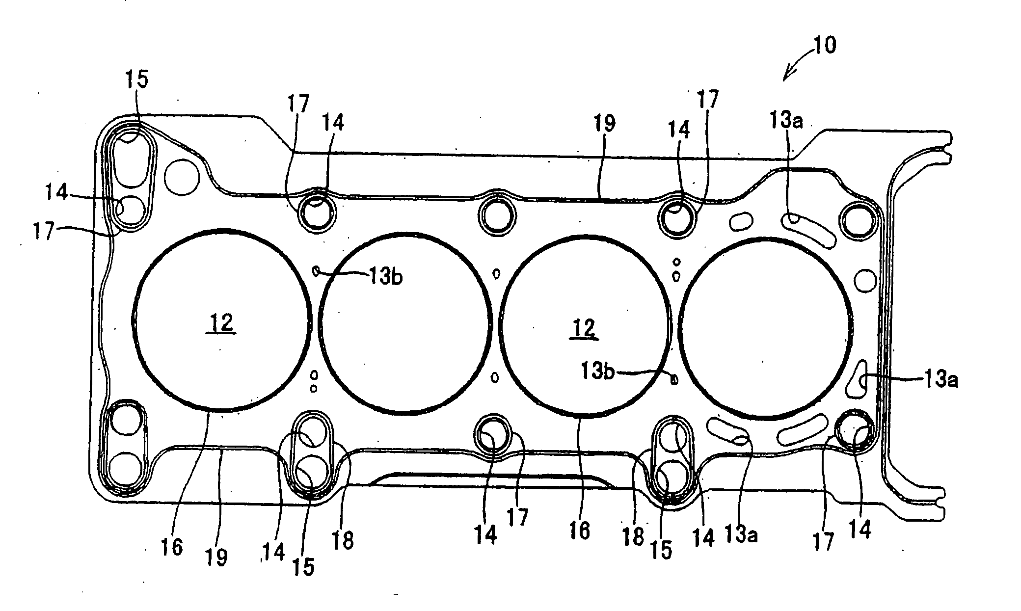
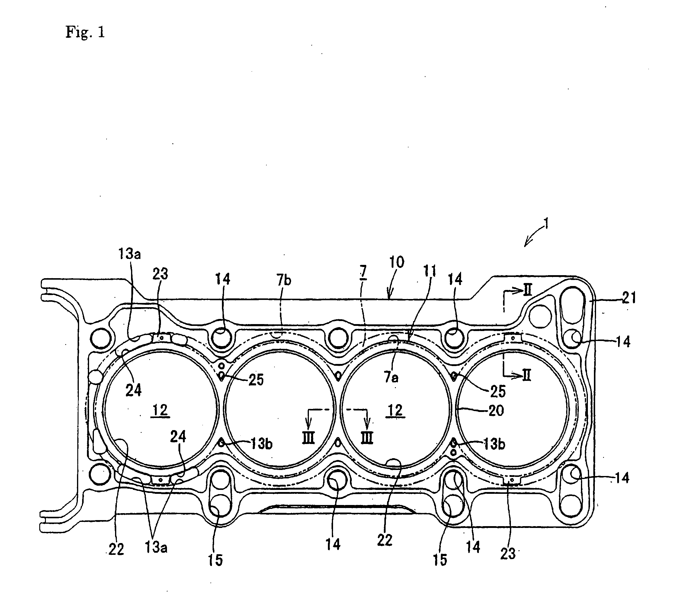
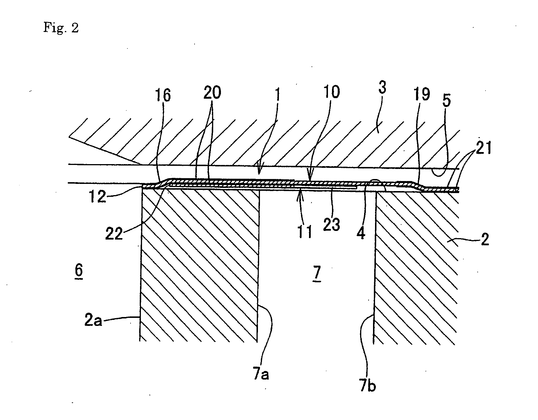
[0041] A metal gasket 1 shown in FIGS. 1 to 4 is a metal gasket for multi-cylinder in-line engines. This metal gasket 1 is disposed between connecting surfaces 4, 5 of a cylinder block 2 and cylinder head 3 to seal the both connecting surfaces 4, 5 at a combustion chamber 6, water jacket 7 and lubricant path (not shown). The metal gasket 1 according to the present invention can be used in engines with a cylinder block of cast iron and engines having a cylinder block and a cylinder head based on light alloy such as aluminum alloy and magnesium alloy. In this embodiment, a description is provided as to the case in which the present invention is applied to an engine having the open deck-type cylinder block 2 in which the top side of the water jacket 7 is opened and the cylinder block 2 and cylinder head 3 are formed of aluminum alloy. However, the present invention is also applicab...


PUM


Abstract

To provide a metal gasket that can be manufactured at an inexpensive cost and provides sufficient sealing performance around a combustion chamber while preventing a bore bead from fully bending. A metal gasket 1 is constructed from one or more gasket component sheets 10 with an opening 12 formed at a position corresponding to a combustion chamber 6 of an engine, and at least one gasket component sheet 10 has a bore bead 16 formed so as to surround the opening 12. In this metal gasket, a shim sheet 11 for controlling the full bending of the bore bead 16 is fixed to the gasket component sheet 10 in an area between the outer peripheral edge of the bore bead 16 and the inner periphery 7a of a water jacket 7 formed on a cylinder block 2 of the engine.

Description

[0001] The present invention relates to metal gaskets that can be suitably used in automobile engines. BACKGROUND OF THE INVENTION [0002] 1. Field of the Invention [0003] Metal gaskets employed for automobile engines are constructed from one or more gasket component sheets. The gasket component sheet has an opening formed so as to correspond to a combustion chamber, a bore bead formed so as to surround the opening, and a stopper formed around the inner periphery of the bore bead, thereby preventing permanent setting of the bore bead due to its full bending. [0004] 2. Description of the Related Art [0005] Stoppers have been proposed and become commonplace in which a peripheral edge of an opening in a gasket component sheet is folded back and the folded portion is utilized as a stopper. Forming the stopper around the inner periphery of the bore bead in this way prevents permanent setting of the bore bead due to its full bending, but a surface pressure on the deck of a cylinder block a...

Claims


Application Information

Patent Timeline
IPC IPC(8): F16J15/08F02F11/00
CPCF16J15/0825
Inventor UMEHARA, KEISUKE
Owner KOKUSAN BUHIN INDS
Why Eureka
Try Eureka