Electric machine having a liquid-cooled rotor

a technology of electric machines and rotating parts, which is applied in the direction of magnetic circuit rotating parts, magnetic circuit shapes/forms/construction, electric devices, etc., can solve the problems of power output of electric machines, the capacity of electric machines to dissipate heat, and the removal of too little hea

Active Publication Date: 2008-01-31
CATERPILLAR INC
View PDF21 Cites 122 Cited by
  • Summary
  • Abstract
  • Description
  • Claims
  • Application Information

AI Technical Summary

Problems solved by technology

One of the limitations on the power output of the electric machines may be the capacity of the electric machine to dissipate this heat.
Although the radially-bored passageways of the rotor shaft may facilitate some heat removal from portions of the excitation-type AC generator, they may remove too little heat, and the removal of h...

Method used


Image

  • Electric machine having a liquid-cooled rotor
  • Electric machine having a liquid-cooled rotor
  • Electric machine having a liquid-cooled rotor

Examples


Embodiment Construction

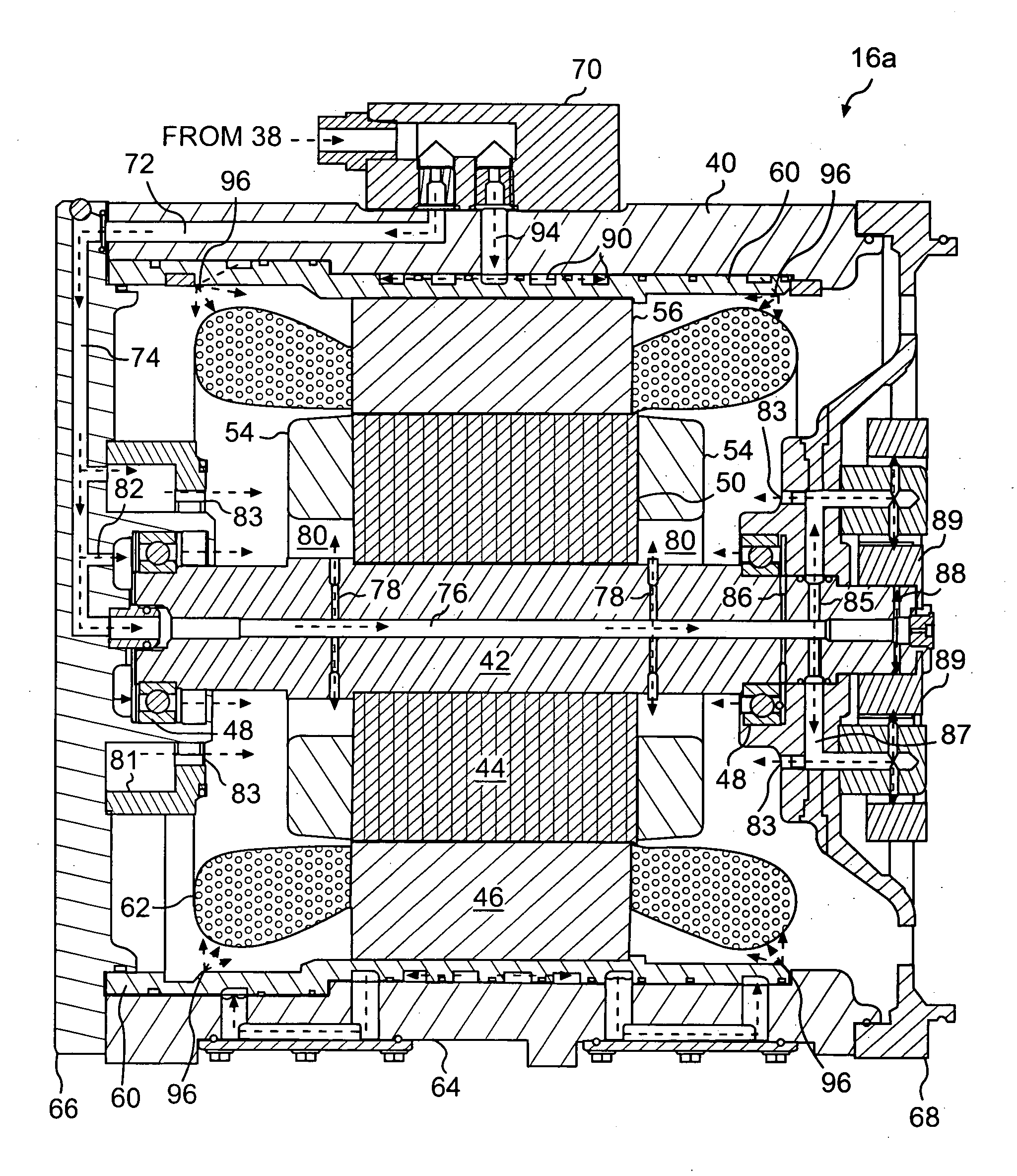
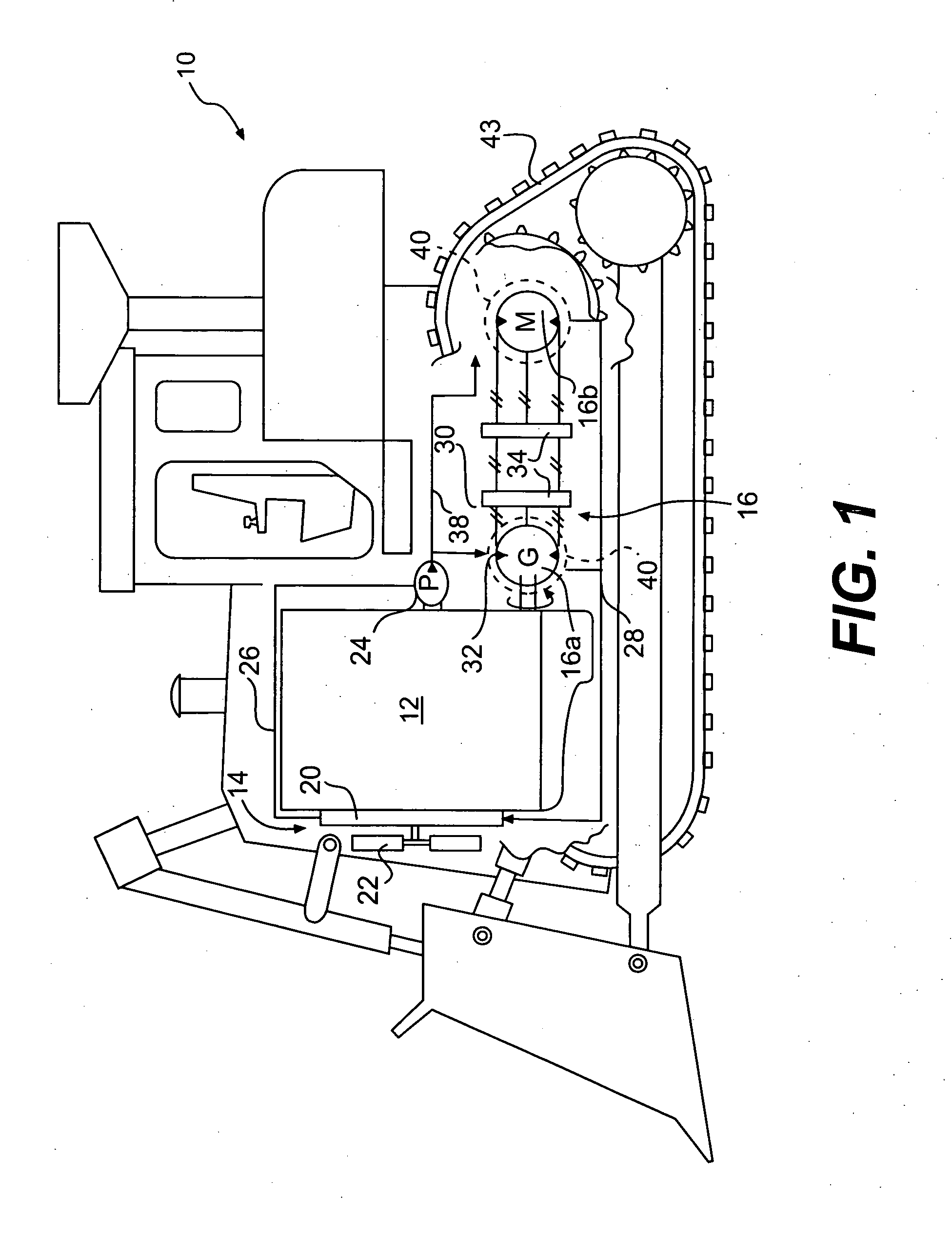
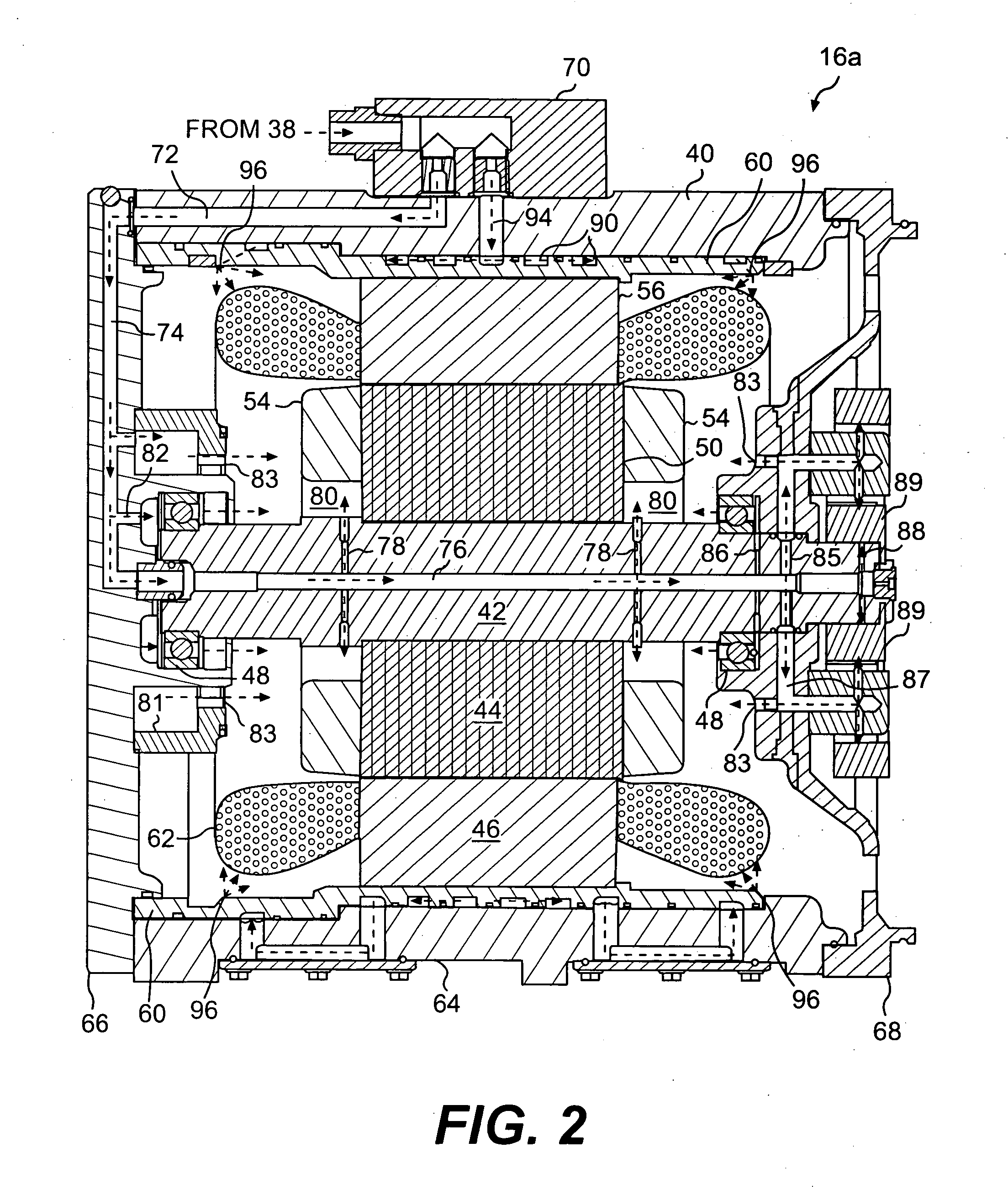
[0011]FIG. 1 illustrates an exemplary power system 10 having a power source 12, a cooling circuit 14, and an electric machine 16. Power system 10 may form a portion of a mobile vehicle such as, for example, a dozer, an articulated truck, an excavator, or any other mobile vehicle known in the art, with electric machine 16 functioning as the main propulsion unit. It is also contemplated that power system 10 may form a portion of a stationary machine such as a generator set, a pump, or any other suitable stationary machine.

[0012]Power source 12 may include a combustion engine operable to produce a rotational mechanical output. For example, power source 12 may include a diesel engine, a gasoline engine, a gaseous fuel-powered engine, or any other type of engine apparent to one skilled in the art. It is also contemplated that power source 12 may alternatively embody a non-combustion source of power such as a fuel cell, a battery, or any other source of power known in the art.

[0013]Coolin...


PUM


Abstract

An electric machine for a power system is disclosed. The electric machine has a housing with a first end cap and a second end cap. The first end cap has a first fluid passageway, and the second end cap has a second fluid passageway. The electric machine also has a stator fixedly disposed within the housing, and a rotor rotationally disposed radially inward from the stator. The rotor has an axial passageway fluidly communicating the first fluid passageway with the second fluid passageway.

Description

TECHNICAL FIELD [0001]The present disclosure relates generally to an electric machine and, more particularly, to an electric machine having a liquid-cooled rotor.BACKGROUND [0002]Electric machines such as, for example, motors and generators may be used to generate mechanical power in response to an electrical input or to generate electrical power in response to a mechanical input. Magnetic, resistive, and mechanical losses within the motors and generators during mechanical and electrical power generation cause a build up of heat, which may be dissipated to avoid malfunction and / or failure of the electric machine. One of the limitations on the power output of the electric machines may be the capacity of the electric machine to dissipate this heat.[0003]One method of dissipating heat within a generator includes directing a cooling medium into the generator via a rotor. For example, U.S. Pat. No. 5,019,733 (the '733 patent) to Kano et al. teaches an excitation-type AC generator having ...

Claims


Application Information

Patent Timeline
IPC IPC(8): H02K9/00H02K1/32H02K5/16
CPCH02K1/32H02K5/1732H02K5/20H02K9/19B60L1/02B60L3/0061Y02T10/641B60L2200/40B60L2240/36Y02T10/7077Y02T90/16Y02T10/6217B60L11/123B60L50/61Y02T10/62Y02T10/64Y02T10/70H02K5/203Y02T10/7072
Inventor IUND, TREVOR N.WOOKEY, ROYBAUMANN, JONATHAN MATTHEWDAMES, MATTHEW
Owner CATERPILLAR INC
Why Eureka
Try Eureka