
Image pickup apparatus

a technology of image pickup and ccd sensor, which is applied in the field of image pickup apparatus, can solve the problems of reducing the cell size of ccd sensor, affecting image quality, and degrading image quality, so as to prevent light diffraction, suppress luminance shock, and prevent degradation of resolution

Active Publication Date: 2008-01-31
CANON KK
View PDF5 Cites 15 Cited by
  • Summary
  • Abstract
  • Description
  • Claims
  • Application Information

AI Technical Summary

Benefits of technology

The present invention provides an image pickup apparatus that can prevent degradation of resolution during still image shooting and maintain dynamic range of exposure control during both still image and moving image shooting. It also ensures continuous luminance not only in a still image but also in a moving image. The apparatus includes an image pickup element, a diaphragm mechanism, a filter, and a controller. The filter can be opened and closed to adjust the amount of light incident on the image pickup element. The speed at which the filter closes can be controlled to prevent luminance shock and ensure the continuity of luminance. The controller can also adjust the aperture of the diaphragm mechanism and the size of the aperture based on the transparent portion of the filter. Overall, the image pickup apparatus provides improved image quality and stability during both still and moving image shooting.

Problems solved by technology

Recently, the cell size of a CCD sensor has been reduced according to reduction of the size of a video camera, and this makes image quality liable to be adversely affected by light diffraction.
The luminance shock not only degrades image quality but also becomes a cause of missing a perfect moment to pick up an image.
Although the luminance shock does not actually damage the result of still image shooting insofar as it occurs on a monitor screen used during still image shooting, if the luminance shock occurs during moving image shooting, continuity of luminance is lost.

Method used


Image

  • Image pickup apparatus
  • Image pickup apparatus
  • Image pickup apparatus

Examples


Embodiment Construction

[0054]The present invention will now be described in detail below with reference to the accompanying drawings showing preferred embodiment thereof.

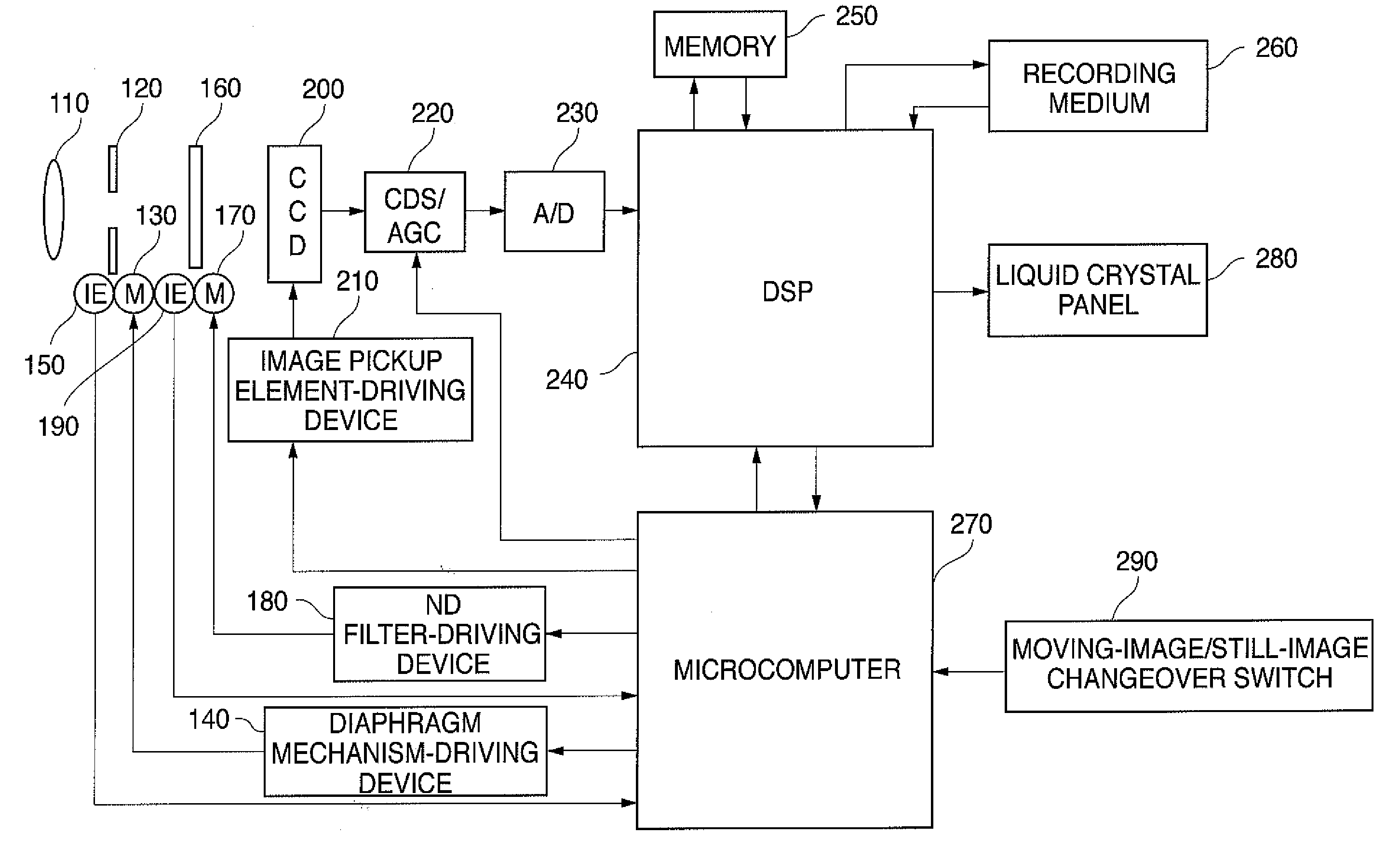
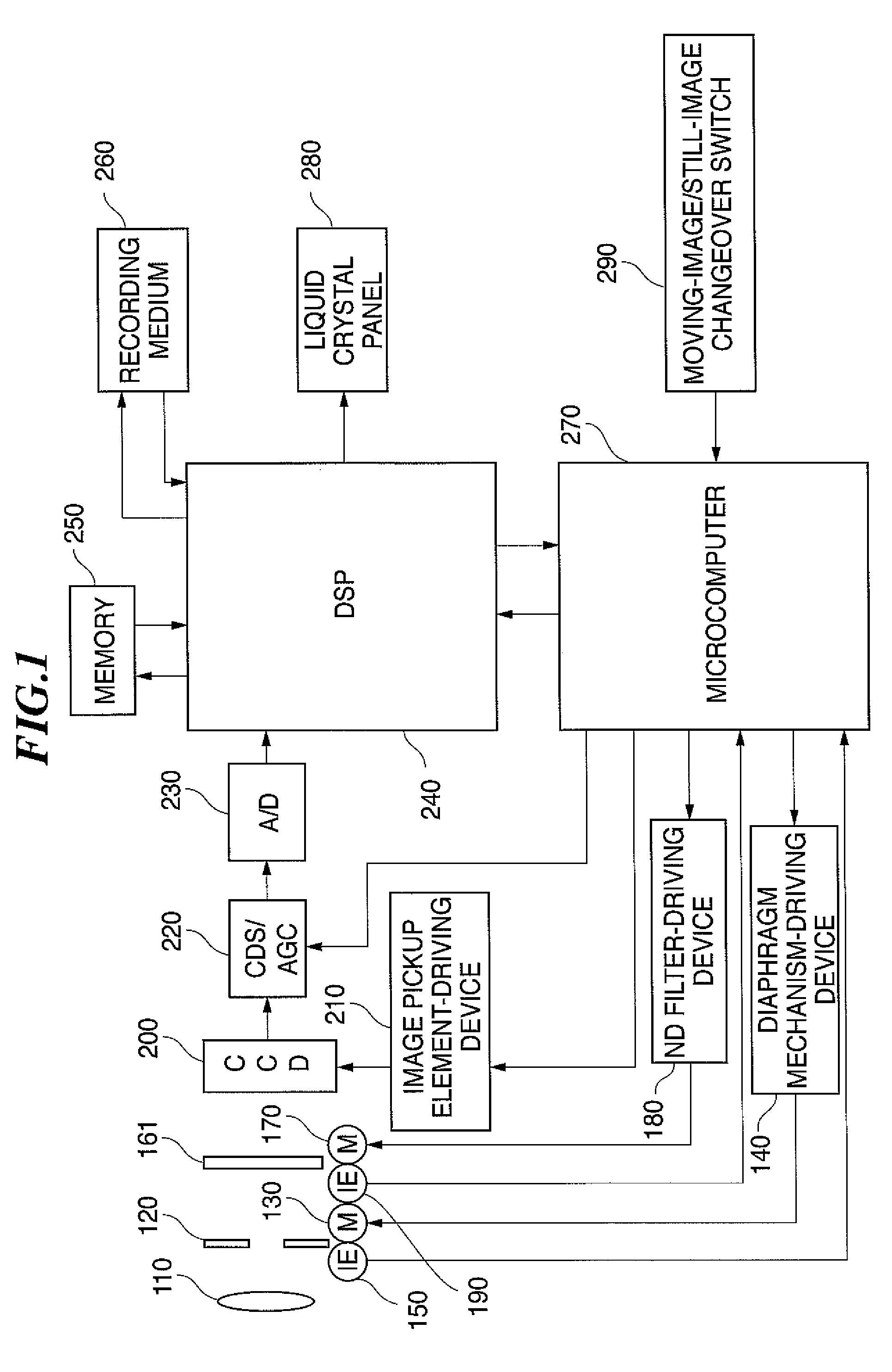
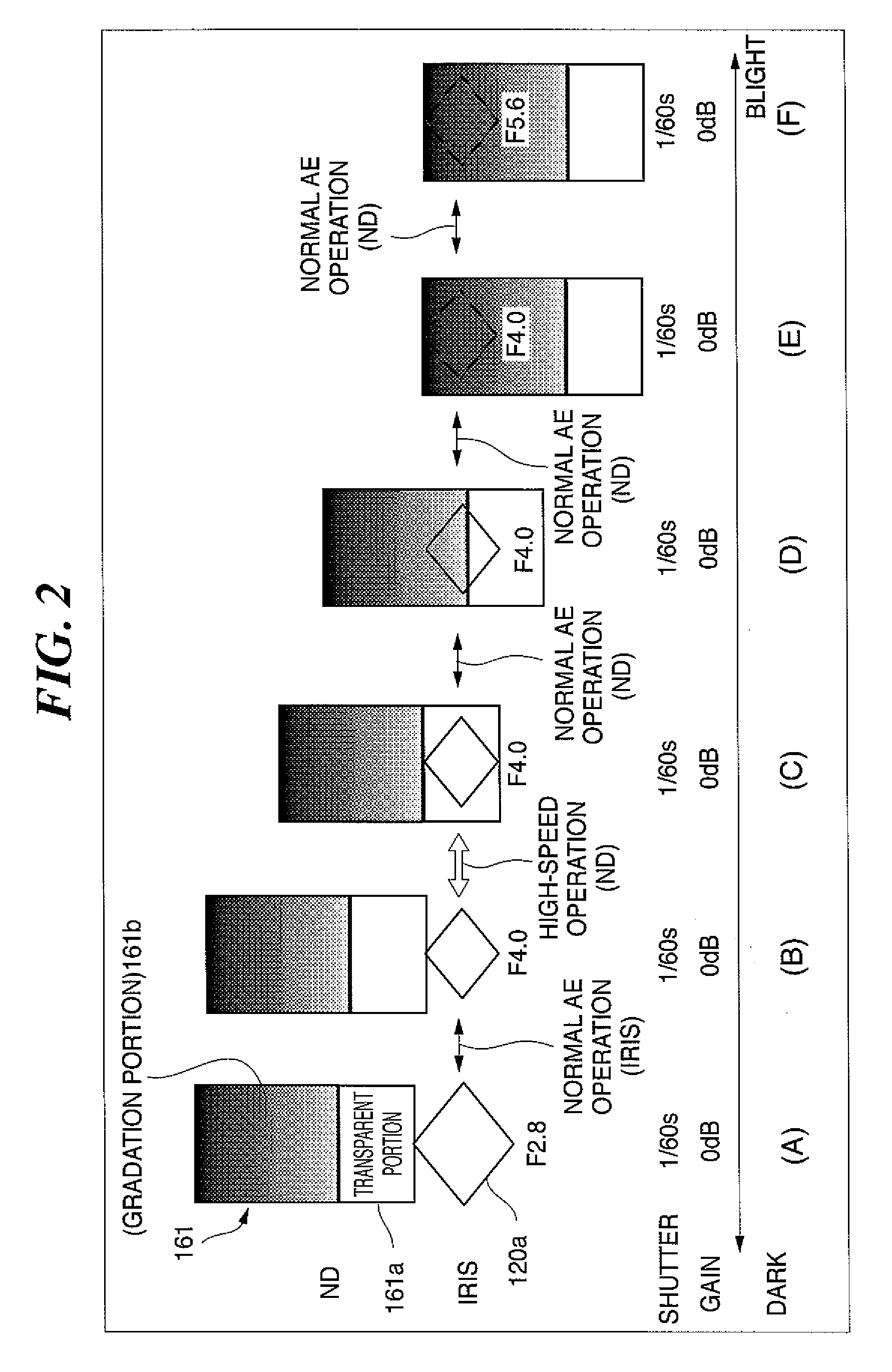
[0055]FIG. 1 is a schematic block diagram of an image pickup apparatus according to an embodiment of the present invention. FIG. 2 is a diagram which is useful in explaining an example of a method of controlling an ND filter. FIG. 3 is a diagram which is useful in explaining the relationship between the size of a transparent portion of the ND filter and the size of an aperture of a diaphragm mechanism of the ND filter. FIG. 4 is a graph showing the relationship between an ND filter control value and an ND filter control position. FIG. 5 is a schematic cross-sectional view of the ND filter. FIG. 6 is a flowchart which is useful in explaining an example of the operation of the image pickup apparatus according to the embodiment. It should be noted that in the present embodiment, for the basic construction of the image pickup apparatus, the c...


PUM


Abstract

An image pickup apparatus which is capable of preventing light diffraction from being caused by a density step or a thickness step of a filter, thereby preventing degradation of resolution during still image shooting, and securing the dynamic range of exposure control during both moving image shooting and still image shooting. In the image pickup apparatus, an image pickup element converts light incident thereon from a lens into an electric signal. A diaphragm mechanism changes the amount of light incident on the image pickup element. An ND filter covers an aperture of the diaphragm mechanism such that the aperture can be opened and closed, thereby adjusting the amount of light incident on the image pickup element after passing through the aperture. A controller controls a closing operation of the ND filter for closing the aperture, such that the closing operation is performed at different speeds between when a gradation portion of the ND filter covers the aperture and when a transparent portion of the ND filter covers the aperture.

Description

BACKGROUND OF THE INVENTION[0001]1. Field of the Invention[0002]The present invention relates to an image pickup apparatus, such as a video camera, and more particularly to an image pickup apparatus equipped with an ND filter for adjusting the amount of light incident on an image pickup element from the aperture of a diaphragm mechanism.[0003]2. Description of the Related Art[0004]Recently, the cell size of a CCD sensor has been reduced according to reduction of the size of a video camera, and this makes image quality liable to be adversely affected by light diffraction. This results in a decrease in the upper limit of the F number which is indicative of a degree of stopping down of the aperture of a diaphragm mechanism that controls exposure. To reduce adverse influence of the light diffraction on image quality even by a slight degree, differently from the conventional technique in which the diaphragm mechanism and an ND (Neutral Density) filter attached to the diaphragm mechanism ...

Claims


Application Information

Patent Timeline
Patent Type & Authority Applications(United States)
IPC IPC(8): H04N5/238H04N23/75
CPCH04N5/232H04N5/238H04N5/23245H04N23/60H04N23/667H04N23/75
Inventor IKEDA, TAKESHI
Owner CANON KK
Learn More