Illuminating Unit and Imaging Apparatus

a technology of illumination unit and imaging apparatus, which is applied in the direction of optical radiation measurement, instruments, spectrometry/spectrophotometry/monochromators, etc., can solve the problems of unevenness of the color of the tooth, unevenness of the paint of an object, and uneven spatial light distribution characteristics of the led light, so as to reduce the amount of light in a direction along the optical axis, and measure with accuracy.

Inactive Publication Date: 2008-01-31
OLYMPUS CORP
View PDF0 Cites 20 Cited by
  • Summary
  • Abstract
  • Description
  • Claims
  • Application Information

AI Technical Summary

Benefits of technology

[0015] There is shown an effect that the imaging apparatus according to the present invention can measure with high accuracy a color distribution of a surface of an object, in which a light intensity distribution on a predetermined surface in a direction substantially perpendicular to an optical axis is uniform, and a change in amount of light in a direction along the optical axis is reduced. Moreover, there is shown an effect that the imaging apparatus according to the present invention is small sized, and can measure with accuracy a color distribution of a surface of an object by a bright diffused light.

Problems solved by technology

Moreover, based on measurement results, an unevenness of the gloss, an unevenness of the color of the tooth, and an unevenness of the paint of an object is calculated.
However, normally, spatial light distribution characteristics of the light from the LED are not uniform.
Therefore, the intensity distribution of the light from the LED has non-uniformity to certain extent.
As a result of this, the color distribution of the surface of the object cannot be measured accurately.
At this time, the imaging apparatus is not fixed mechanically.
Moreover, in the structure in Japanese Patent No. 3218601, when a gap between a color measuring apparatus and the object is changed, the unevenness in the light intensity distribution of the illuminated light is increased.
Thus, the structure in the Japanese Patent No. 3218601 is a problem due to an occurrence of the uneven light intensity distribution caused by a change in the imaging distance along the direction of the optical axis.
This problem becomes even more remarkable when the object is three-dimensional.
As a result of this, when the specularly reflected light (which is reflected) from the surface is incident on an imaging optical system, the color distribution of the surface cannot be measured accurately.
As a result of this, the unevenness of the color of the surface of the object cannot be measured accurately, which is a problem.
Therefore, in the structure of the conventional technology, in a case of the object having a gloss, this problem becomes even more remarkable.
As a result of this, there is a problem that a size of the imaging apparatus becomes big.

Method used


Image

  • Illuminating Unit and Imaging Apparatus
  • Illuminating Unit and Imaging Apparatus
  • Illuminating Unit and Imaging Apparatus

Examples


first embodiment

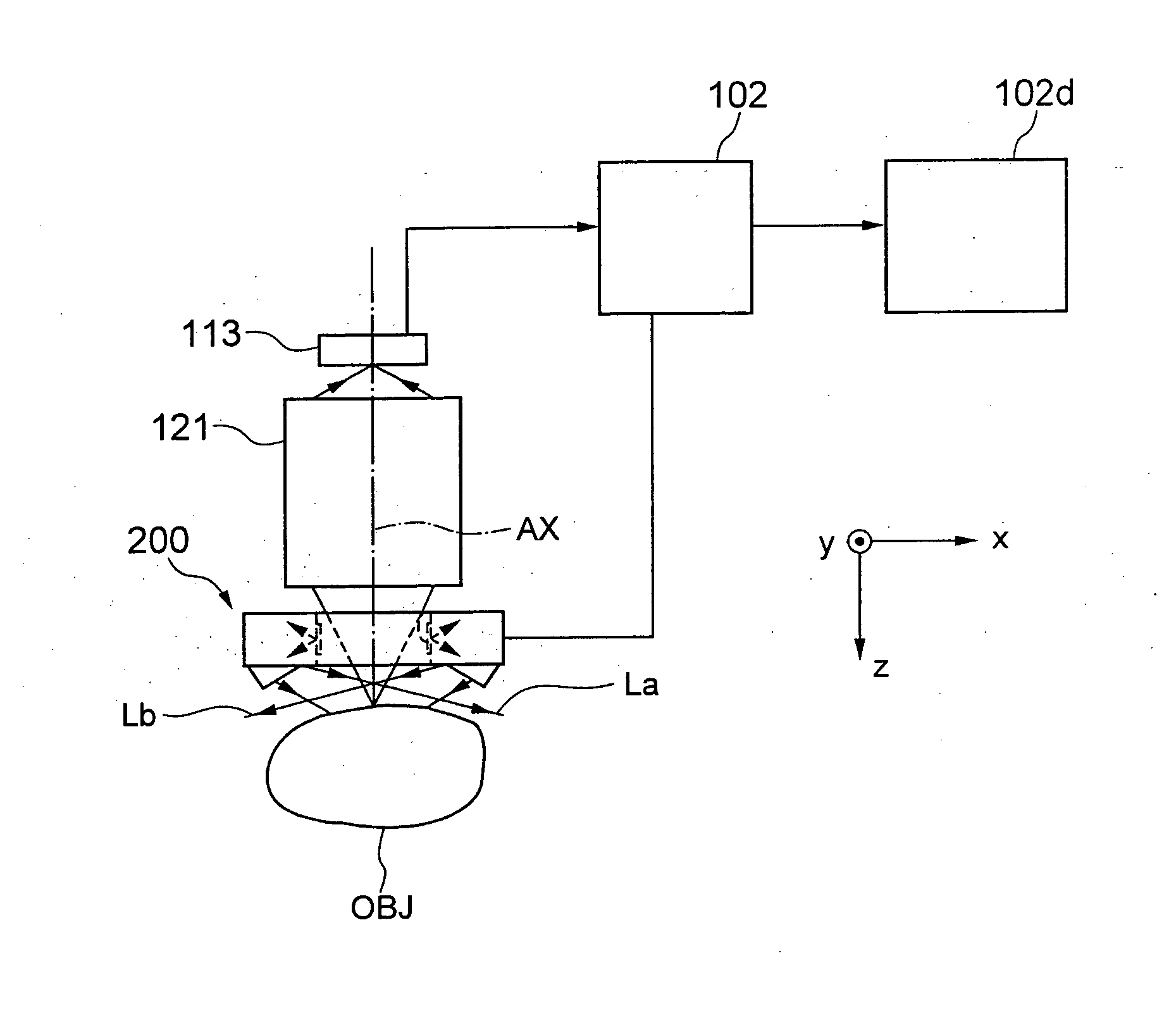
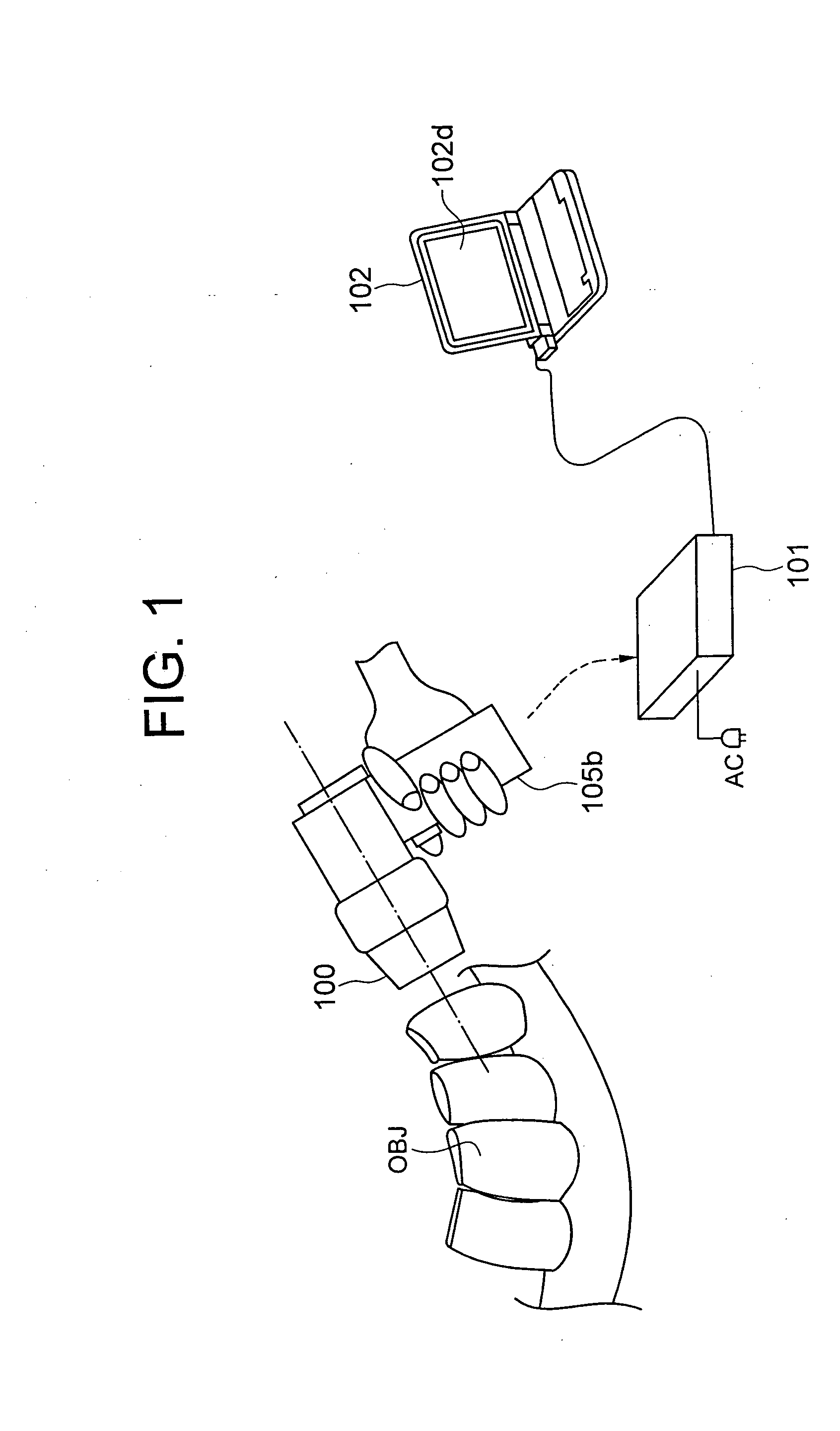
[0036]FIG. 1 shows a formation for use of an imaging apparatus 100. The imaging apparatus 100 is an apparatus used for application of measuring accurately a gloss and a color of a tooth of a human being as an object OBJ, for example.

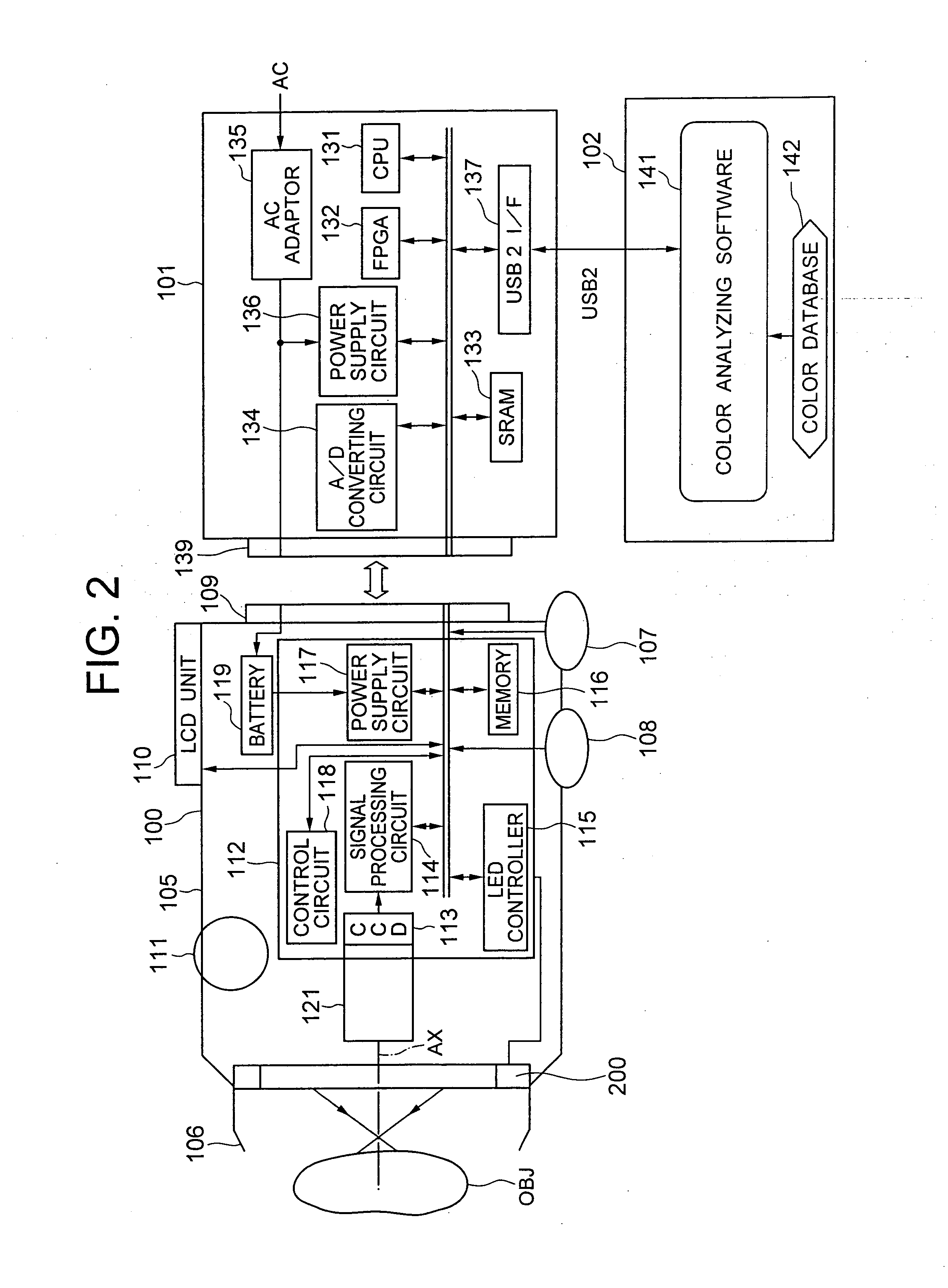
[0037] As shown in FIG. 1, a system which uses the imaging apparatus 100 includes the imaging apparatus 100, a cradle 101, and a computer 102. The imaging apparatus 100 performs imaging of the object OBJ such as a tooth. After the imaging, the imaging apparatus 100 is mounted on the cradle 102. Accordingly, the cradle 101 is electrically connected to the imaging apparatus 100. By electrically connecting the cradle 101 to the imaging apparatus 100, the cradle 102 receives imaging data from the imaging apparatus 100. At the same time, the cradle 101 charges the imaging apparatus 100.

[0038] The computer 102 is connected to the cradle 101. The computer 102 receives the imaging data via the cradle 101. Next, the computer 102 performs a predetermined analysi...

second embodiment

[0079] A structure of an illuminating unit 1200 according to a second embodiment will be described by referring to FIG. 11 and FIG. 12. Same reference numerals are assigned to components same as in the first embodiment, and the description to be repeated is omitted. FIG. 11 shows a structure of the illuminating unit 1200 as seen from the side of the object OBJ. Moreover, FIG. 12 shows a cross-sectional structure of the illuminating unit 1200. As shown in FIG. 11, the diffusing section 211 is formed to have an annular cylindrical shape. The light source section 210 is disposed on an inner circumferential side of the annular cylindrical shape. The light source section 210 includes the LEDs 210a, 210b, 210c, 210d, 210e, 210f, 210g, and 210h. In FIG. 11, two LEDs each of the LED 210a, 210b, and 210c are shown. Thus, the illuminating unit 1200 has total of 12 LEDs disposed at substantially equal interval. Each of the LEDs 210a to 210h is structured to emit light toward the outer circumfe...

third embodiment

[0083] A structure of an illuminating unit 1300 according to a third embodiment will be described below by referring to FIG. 13. Same reference numerals are assigned to components same as in the first and the second embodiment, and the description to be repeated is omitted. FIG. 13 shows a structure of the illuminating unit 1300 as viewed from the side of the object OBJ.

[0084] The diffusing section 211 is formed to have a continuous cylindrical shape encircling the optical axis AX which is a predetermined axis. Moreover, by the cylindrical shaped diffusing section 211, a space of a predetermined shape is formed near the optical axis AX which is the predetermined axis. Light from the illuminating unit 1300 is reflected at the surface of the object OBJ, and scattered. The scattered light is passed through the space having the predetermined shape, of the illuminating unit 1300, and is incident on the imaging optical system 121. Thus, it is possible to dispose the illuminating unit 130...


PUM


Abstract

There is provided a small sized imaging apparatus which can measure with high accuracy a color distribution of a surface of an object, in which a light intensity distribution on a predetermined surface in a direction substantially perpendicular to an optical axis is uniform, and a change in an amount of light in a direction along the optical axis is reduced, and an illuminating unit which used in this imaging apparatus. (The imaging apparatus) Includes a light source section (210) which supplies illuminating light, a diffusing section (211) which diffuses by reflecting the illuminating light from the light source section (210), and aperture sections (212a and 212b) which allow to emerge diffused illuminating light, and the aperture sections (212a and 212b) has an aperture diameter D which allows the diffused illuminating light to emerge as a substantially parallel light.

Description

TECHNICAL FIELD [0001] The present invention relates to an illuminating unit, and an imaging apparatus which includes the illuminating unit. BACKGROUND ART [0002] For example, paint on a surface of a passenger automobile, a gloss and a color of a tooth of a human being has been hitherto measured over a predetermined range. Moreover, based on measurement results, an unevenness of the gloss, an unevenness of the color of the tooth, and an unevenness of the paint of an object is calculated. Particularly, in a field of dental treatment, many a times, a dentist makes a judgment of the color of tooth, a color tone, and the gloss. For this, a predetermined range of tooth is illuminated by an illuminating unit. A light emitting diode (hereinafter called as “LED”) can be used as a light source of the illuminating unit. A structure of a color measuring apparatus in which the LED is used is proposed in Japanese Patent No. 3218601. [0003] The unevenness of the color, the color tone, and the glo...

Claims


Application Information

Patent Timeline
Patent Type & Authority Applications(United States)
IPC IPC(8): G02B5/02A61B1/24A61C19/04G01J3/10G03B15/02
CPCA61B1/24G01J3/0216G01J3/0251G01J3/0264G01J3/0272A61B1/0684G01J3/501G01J3/508A61B1/063A61B1/0676G01J3/10
Inventor OKAMURA, TOSHIROWADA, TORU
Owner OLYMPUS CORP
Why Eureka
Try Eureka