
Method for Producing a Plastic-Coasted Stamped Grid, and Plastic-Coated Stamped Grid

a technology of stamped grids and grids, applied in the direction of electrical apparatus construction details, manufacturing tools, coupling device connections, etc., can solve the problems of metal being exposed to the stamped grid, and affecting the effect of the effect of the stamped grid

Inactive Publication Date: 2008-01-31
ROBERT BOSCH GMBH
View PDF7 Cites 3 Cited by
  • Summary
  • Abstract
  • Description
  • Claims
  • Application Information

AI Technical Summary

Benefits of technology

The invention is about a method for producing a plastic-coated stamped grid with electronic components embedded in it. The method involves fixing the stamped grid in an injection mold during the injection molding process. This has the advantage that it ensures the shape of the stamped grid is preserved during the process. The use of plastic elements at fixation points seals off the grid, providing better protection against environmental conditions. The plastic-coated stamped grid produced using this method has the advantage that it is open in the areas where it is used, making it easier to monitor and control its quality. The refinements of the method include using a two-component injection mold and a structural part to hold the grid in place during the process. The plastic-coated stamped grid is embedded in a housing of plastic, which is produced by the two-component injection molding process. The housing has orifices that align with one another, making it easier to visually inspect and control the quality of the grid.

Problems solved by technology

The use of the dies means that the stamped grid is not covered with plastic at these points, which can have adverse effects under aggressive environmental conditions to which the metal of the stamped grid can be exposed.

Method used


Image

  • Method for Producing a Plastic-Coasted Stamped Grid, and Plastic-Coated Stamped Grid
  • Method for Producing a Plastic-Coasted Stamped Grid, and Plastic-Coated Stamped Grid

Examples


Embodiment Construction

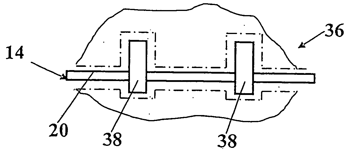
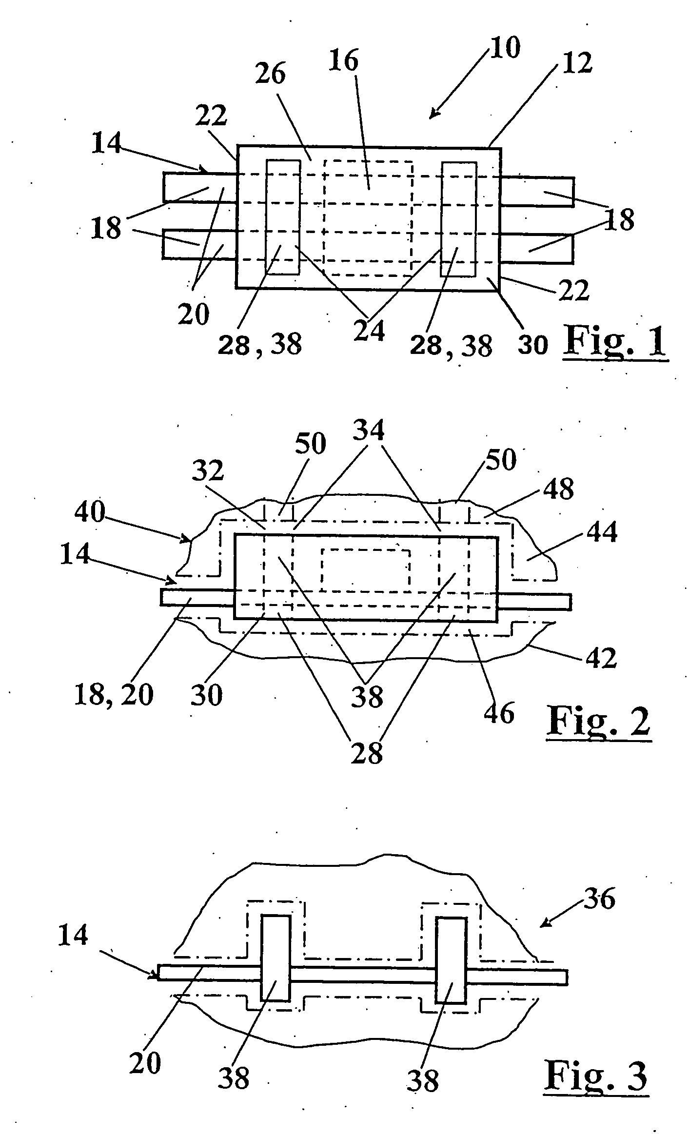
[0019] In FIG. 1, an interference suppressor 10 for an electric motor, not shown, is shown from below. The interference suppressor 10 includes a plastic housing 12 and a stamped grid 14, embedded in it, on which a capacitor 16, optionally combined with a resistor, is disposed. The interference suppressor 10 has four terminals 18, which are formed by two parallel strips 20 of the stamped grid 14 that protrude out of the housing 12 on two diametrically opposed long sides 22. It is also conceivable, instead of the relatively simply constructed interference suppressor 10, to provide a complex control unit that has dozens of terminals 18 and a substantially more-complex stamped grid 14, which has many different structural parts rather than merely capacitors 16. It is also possible for no electronic structural parts whatever to be provided, so that the plastic-coated stamped grid 14 is merely in the form of a plug, for instance. However, it is preferable for electronic components to be di...


PUM

PropertyMeasurementUnit
shapeaaaaaaaaaa
plasticaaaaaaaaaa
miscibilityaaaaaaaaaa

Abstract

A method for producing a plastic-coated stamped grid, and a grid producer thereby on which components are disposed and which is embedded in a plastic housing in an injection mold, with the stamped grid being fixed at a fixation point with a fixation element, so that the shape of the stamped grid is preserved during the injection molding operation. As the fixation element, a plastic element is used, which is enclosed by the injected plastic, so that it seals off the fixation point. The housing is produced with a first and a second component, and the stamped grid is enclosed completely by the second component, but terminals for mechanically and / or electrically connecting the stamped grid are not enclosed. The first component opens out to a first outer side and to a second outer side of the housing.

Description

PRIOR ART [0001] The invention is based on a method for producing a plastic-coated stamped grid and on a plastic-coated stamped grid on which preferably electronic components are disposed, as generically defined by the preambles to the independent claims 1 and 8. [0002] In the known method, the stamped grid is embedded in plastic in an injection mold. During the injection molding operation, the stamped grid is as a rule held in position at a plurality of fixation points by fixation elements. The fixation elements are dies, which are disposed in the injection mold and in pairs firmly hold the stamped grid. As a result, the stamped grid is fixed in its shape, so that the shape of the stamped grid is essentially preserved during the injection molding operation. The use of the dies means that the stamped grid is not covered with plastic at these points, which can have adverse effects under aggressive environmental conditions to which the metal of the stamped grid can be exposed. [0003] ...

Claims


Application Information

Patent Timeline
Patent Type & Authority Applications(United States)
IPC IPC(8): H05K7/00B29C39/00B29C45/14H01R13/405H01R43/24
CPCH01R43/24H01R13/405
Inventor HORBELT, MICHAEL
Owner ROBERT BOSCH GMBH
Learn More