Switching power supply circuit

a power supply circuit and power supply circuit technology, applied in the direction of electric variable regulation, process and machine control, instruments, etc., can solve the problems of increasing the cost and mounting area increasing the cost of the power supply circuit board, and increasing the number of parts. , to achieve the effect of improving the power factor of the switching power supply circuit as a load for the alternating-current power supply, improving the power conversion efficiency characteristics of the switching power supply circuit, and reducing the number of parts

Inactive Publication Date: 2008-01-31
SONY CORP
View PDF9 Cites 13 Cited by
  • Summary
  • Abstract
  • Description
  • Claims
  • Application Information

AI Technical Summary

Benefits of technology

[0037] The choke coil may be formed as a leakage inductance occurring at a primary winding of a choke transformer. The choke transformer may be formed with the primary winding and a secondary winding magnetically loosely coupled with each other, and the current corresponding to the voltage generated in the primary side series resonant capacitor flows via the secondary winding of the choke transformer. Thereby the power factor of the switching power supply circuit as a load for the alternating-current power supply is improved.
[0038] The switching power supply circuit according to one embodiment of the present invention can be provided with a power factor improving function without the active filter. By omitting the active filter, the power conversion efficiency characteristics of the switching power supply circuit are improved. Then, a radiator and the like can be omitted or reduced in size. In addition, as compared with the configuration including the active filter, the number of parts is also reduced greatly. Further, one switching element is used to deal with high power, so that the circuit is reduced in size, weight, and cost. In addition, while the active filter performs hard switching operation, the switching converter according to one embodiment of the present invention, which may be based on a resonant converter, may perform soft switching operation. This greatly reduces switching noise, and thus contributes to reductions in size, weight, and cost of a noise filter. Further, because a plurality of clocks of different frequencies may not exist, a problem of mutual interference due to the plurality of clock frequencies does not occur, reliability is improved, and circuit board pattern design and the like are made easier. Further, the withstand voltage of the switching element can be lowered.

Problems solved by technology

However, the power supply circuit of the configuration shown in FIG. 22 has the following problems.
In addition, the active filter circuit performs hard switching operation, and thus causes much noise.
Thus, measures against noise using a large number of parts are necessary, resulting in increases in cost and mounting area of a board of the power supply circuit.
Therefore, due to the switching operations of the switching element Q103 and the current resonant converter operating on the respective clocks, ground potentials interfere with each other and become unstable, and for example an abnormal oscillation tends to occur.
This also invites for example problems of more difficult circuit design and degradation in reliability.

Method used


Image

  • Switching power supply circuit
  • Switching power supply circuit
  • Switching power supply circuit

Examples


first embodiment

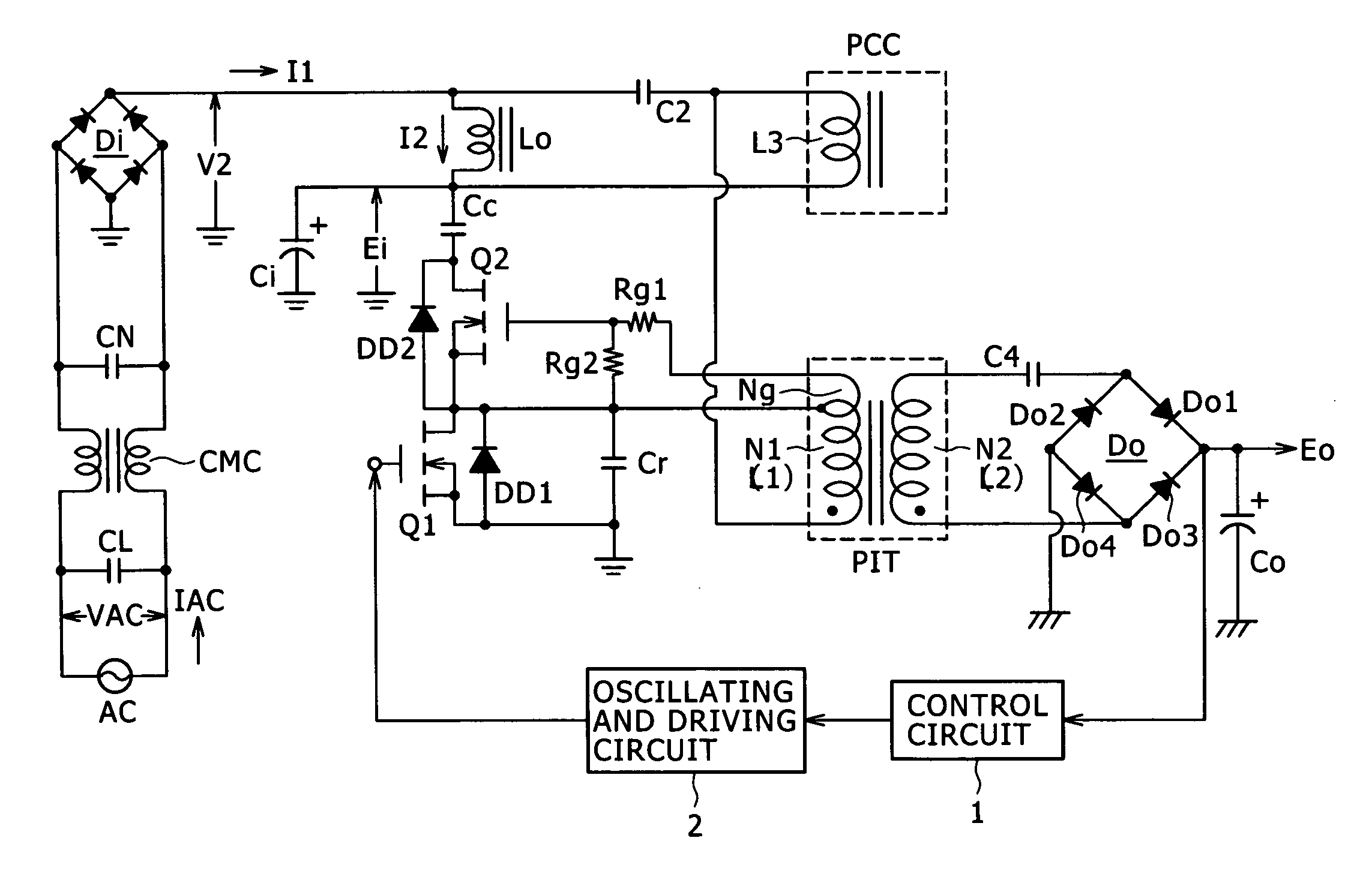
[0079] As the present embodiment, a modification of the above-described class E switching converter is applied to a power supply circuit. An outline of a switching power supply circuit according to a first embodiment shown in FIG. 1 will be described in the following. The switching power supply circuit according to the first embodiment includes: a rectifying and smoothing section, a converter section, and a power factor improving section. The rectifying and smoothing section converts input alternating-current voltage from an alternating-current power supply AC into primary side direct-current voltage. The converter section converts the primary side direct-current voltage from the rectifying and smoothing section into alternating voltage and further converts the alternating voltage into secondary side direct-current voltage. The power factor improving section improves a power factor. The rectifying and smoothing section includes a primary side rectifying element Di, which is supplied...

second embodiment

[0132] In a switching power supply circuit according to a second embodiment shown in FIG. 6, same parts as in the first embodiment are identified by the same reference numerals, and description thereof will be omitted. The switching power supply circuit according to the second embodiment employs same configurations as in the first embodiment in many parts. The second embodiment is different from the first embodiment in that a slow rectifying element capable of rectifying a commercial alternating voltage having a frequency of 50 or 60 Hz is used as a primary side rectifying element Di. In addition, a fast rectifying element D1 is made to function as a rectifying element for making resonance current flowing through a primary side first series resonant circuit and a primary side second series resonant circuit flow in one direction. In order to make the resonance current flowing through the fast rectifying element D1 and having a frequency of a few ten KHz to 200 KHz flow in one directi...

third embodiment

[0134] In a switching power supply circuit according to a third embodiment shown in FIG. 7, same parts as in the first embodiment are identified by the same reference numerals, and description thereof will be omitted. The switching power supply circuit according to the third embodiment employs same configurations as in the first embodiment in many parts. The third embodiment is different from the first embodiment in that a power factor improving section passes a current corresponding to a voltage generated in a primary side series resonant capacitor from an alternating-current power supply via a primary side rectifying element. As for a converter section, the third embodiment is different from the first embodiment in that a choke coil PCC is used between a primary side rectifying element Di and a smoothing capacitor Ci in place of the power factor improving inductance Lo. In addition, the primary winding N1 of a converter transformer PIT is connected to the output side of the primar...


PUM


Abstract

The present invention provides a switching power supply circuit which may include a rectifying and smoothing section, a converter section, and a power factor improving section. The rectifying and smoothing section may include a primary side rectifying element and a smoothing capacitor. The converter section may include a choke coil, a converter transformer, a main switching element, an oscillating and driving circuit, a primary side series resonant capacitor, a primary side parallel resonant capacitor, and an active clamping circuit. The power factor improving section may add and pass a current corresponding to a voltage generated in the primary side series resonant capacitor to the smoothing capacitor via the primary side rectifying element.

Description

CROSS-REFERENCE TO RELATED APPLICATIONS [0001] This application claims priority from Japanese Patent Application No. JP 2006-067730 filed in the Japanese Patent Office on Mar. 13, 2006, the entire content of which is incorporated herein by reference. BACKGROUND OF THE INVENTION [0002] 1. Field of the Invention [0003] The present invention relates to a switching power supply circuit provided as a power supply for various electronic devices. [0004] 2. Description of the Related Art [0005] Most of power supply circuits that rectify commercial alternating-current power and provide desired direct-current voltage have recently been switching type power supply circuits. A switching power supply circuit has a transformer and other devices miniaturized by increasing switching frequency, and is used as a power supply for various electronic devices as a high-power DC-to-DC converter. [0006] The commercial alternating-current power is a sinusoidal alternating voltage. When a smoothing and recti...

Claims


Application Information

Patent Timeline
Patent Type & Authority Applications(United States)
IPC IPC(8): H02M7/219
CPCH02M1/4241Y02B70/126H02M1/4258Y02B70/10H02M3/28
Inventor YASUMURA, MASAYUKI
Owner SONY CORP
Why Eureka
Try Eureka