Impulse Response Measurement Method and Device

a technology of impulse response and measurement method, which is applied in the direction of measurement device, instrument, electrical apparatus, etc., can solve the problems of insufficient energy in the higher frequency band relative to the lower frequency band of the tsp method, and achieve the effects of reducing the s/n ratio, improving the accuracy of measurement, and being well-balanced

Inactive Publication Date: 2008-01-31
WAKAYAMA UNIVERSITY
View PDF4 Cites 13 Cited by
  • Summary
  • Abstract
  • Description
  • Claims
  • Application Information

AI Technical Summary

Benefits of technology

[0027] According to the present invention, by generating as a measuring signal a W-TSP signal having a characteristic of the TSP signal and a characteristic of the Log-TSP signal, measu

Problems solved by technology

However, comparing the Log-TSP method to the TSP method, energy in the higher frequency

Method used


Image

  • Impulse Response Measurement Method and Device
  • Impulse Response Measurement Method and Device
  • Impulse Response Measurement Method and Device

Examples


first embodiment

[0040] The device for impulse response measurement 10 shown in FIGS. 1 and 2 will be described next in detail. FIG. 3 is a block diagram showing the device for impulse response measurement 10. This device for impulse response measurement 10-1 comprises a signal generation unit 21 for generating a W-TSP signal x(t), a D / A conversion unit 22 for converting the W-TSP signal into an analog signal, an A / D conversion unit 23 for converting the signal y(t) into a digital signal, an inverse signal generation unit 24 for generating an inverse W-TSP signal x−1(t) and a convolution unit 25 for calculating an impulse response g(t) by convoluting the signal y(t) mentioned above and the inverse W-TSP signal x−1(t).

[0041] The operations will next be explained. After the beginning of an impulse response measurement, the signal generation unit 21 of the device for impulse response measurement 10-1 generates a W-TSP signal x(t) that can be obtained by transforming onto the time axis an H(k) satisfyin...

second embodiment

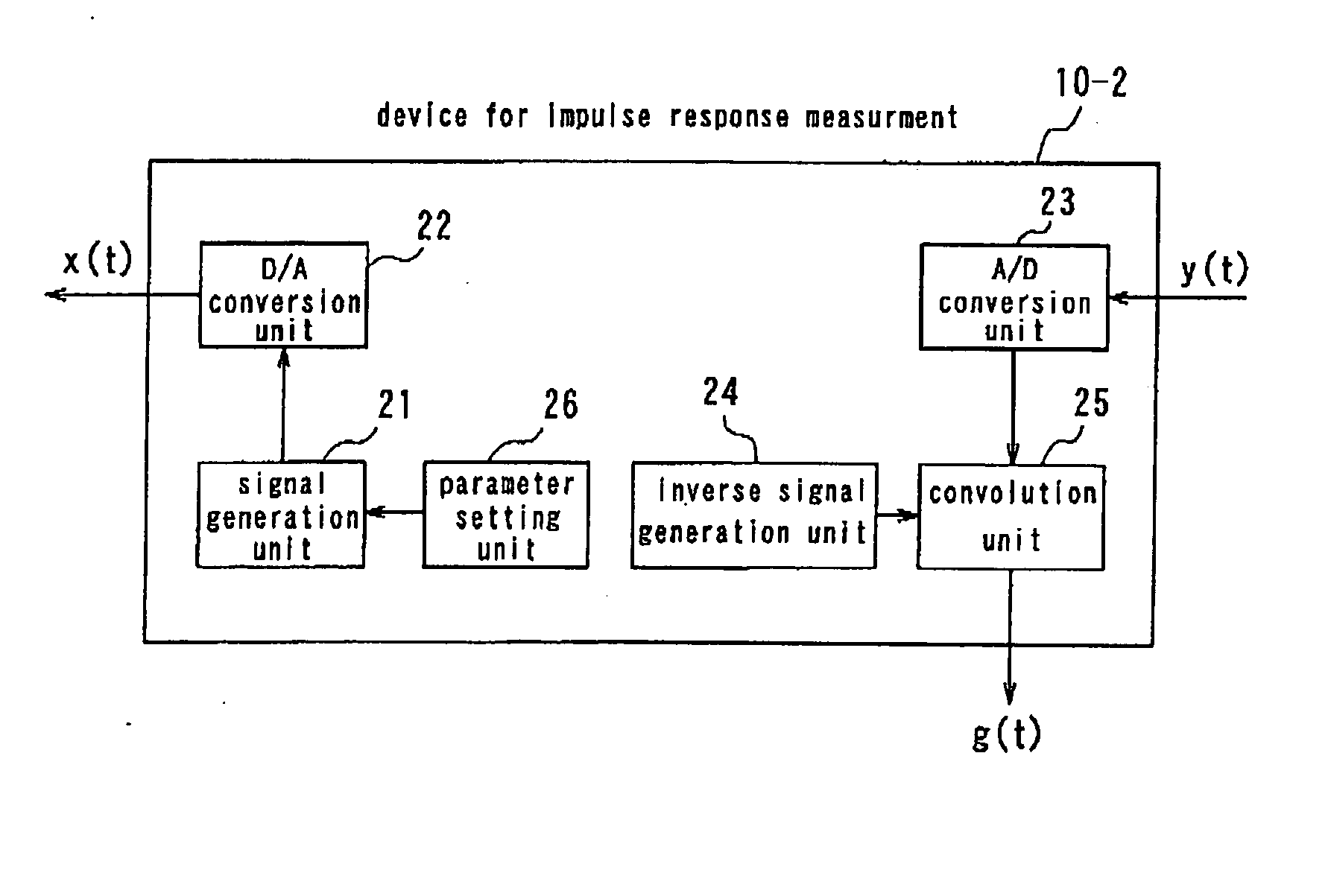
[0042] the device for impulse response measurement will be described with reference to FIG. 4. The device for impulse response measurement 10-2 comprises a parameter setting unit 26 as well as a signal generation unit 21 shown in FIG. 3, a D / A conversion unit 22, an A / D conversion unit 23, an inverse signal generation unit 24 and a convolution unit 25. In FIG. 4, equivalent components are referred to with the same symbols as in FIG. 3, description in detail thereof being omitted.

[0043] The parameter setting unit 26 sets a parameter n (=1, . . . , N / 2) that determines characteristics of the W-TSP signal x(t) and outputs the parameter to the signal generation unit 21. The signal generation unit 21 generates a W-TSP signal x(t) with the use of the parameter n having been set by the parameter setting unit 26. Herein the parameter n may be a number within the range of 1 to N / 2. Referring to formulas (3) to (5), if the parameter n is close to 1, the signal generation unit 21 generates a W...


PUM


Abstract

A method, device, system, program and recording medium for impulse response measurement which can improve a measurement accuracy without lowering the S/N ratio over the whole range, from lower frequencies to higher frequencies, of a measuring signal are provided. A signal generation unit (21) of a device for impulse response measurement (10-1) generates a W-TSP signal (x(t)) having characteristics of a TSP signal and a Log-TSP signal. A D/A conversion unit (22) converts the digital signal (x(t)) into an analog signal (x(t)) and outputs the converted signal to a headphone (2) or a speaker (5). An A/D conversion unit (23) inputs an analog signal (y(t)) received by a microphone (3) or a microphone (6) and converts the inputted signal into a digital signal (y(t)). An inverse signal generation unit (24) generates an inverse W-TSP signal (x(t)). A convolution unit (25) convolutes the signal (y(t)) and the inverse W-TSP signal (x−1(t)) thereby to calculate an impulse response (g(t)).

Description

FIELD OF THE INVENTION [0001] The present invention relates to a method for an impulse response measurement using the cross-correlation method, and particularly to a method for measuring an impulse response as a basis of acoustic transmission properties of an audio instrument or a room, using as a measuring signal, for example, an improved TSP (Time Stretched Pulses) signal. BACKGROUND OF THE INVENTION [0002] An impulse response measurement of an acoustic transmission system of an audio instrument such as a headphone or a speaker or a room is of great importance in obtaining the audio transmission properties thereof. Among methods for measuring such an impulse response are, for example, the M sequence (Maximum length sequence) method and the TSP method. In the M sequence method, the impulse response can be obtained very quickly with the use of an M sequence signal as a sound source signal and fast Hadamard transformation in calculating the cross-correlation between the sound source ...

Claims


Application Information

Patent Timeline
IPC IPC(8): H04R29/00
CPCG01H3/00H04R29/00G01H15/00
Inventor MORISE, MASANORIIRINO, TOSHIOKAWAHARA, HIDEKIBANNO, HIDEKI
Owner WAKAYAMA UNIVERSITY
Why Eureka
Try Eureka