Recording device

a recording device and recording technology, applied in the field of recording devices, can solve the problems of high cost, inconvenient input of region codes, and difficulty in obtaining service lists, and achieve the effect of convenient channel setting

Inactive Publication Date: 2008-01-31
FUNAI ELECTRIC CO LTD
View PDF4 Cites 2 Cited by
  • Summary
  • Abstract
  • Description
  • Claims
  • Application Information

AI Technical Summary

Benefits of technology

[0017]An object of the present invention is to provide a recording device having high convenience that does not require a user to set channel information.
[0019]According to this structure, when the recording device is connected to a power source and a main power is supplied, the current position identifying portion obtains position information of the recording device by using GPS satellites. Then, a region where the recording device is installed (e.g., a prefecture) is decided based on the obtained position information. Then, channel information that is appropriate for the decided region is read out from a storage medium such as a memory, and channel setting of the receiving portion such as a tuner of the recording device is performed by using the channel information thus read out. Since the GPS reception is performed, the broadcasting electric wave is not influenced by reception conditions, and the user is not required to perform the manual setting of channel information. Thus, a burden of work can be reduced, and setting errors of the channel information can be prevented.
[0023]Therefore, even if the device cannot obtain the current position automatically, the user can set the channel information easily only by entering the code number to perform channel information settings.
[0025]Therefore, if the region of installation of the device is so close to other region that there is a possibility of an error in the case where the selection of region is performed automatically, the user can set an appropriate region code easily from among the plurality of region code candidates. Further, also in the case where the user's device can receive a channel in a neighboring region more easily due to the terrain or the like, the channel setting can be performed easily by selecting a desired code number manually.

Problems solved by technology

However, if the region of installation is changed because of moving house or the like, it is inconveniently required to enter the region code again.
However, the television receiving apparatus disclosed in the JP-A-2006-086730 cannot support a difference of the channel information between regions although it can support a difference of the modulation format between regions.
In addition, the digital broadcasting receiver disclosed in JP-A-2005-064718 requires developing a new digital tuner that can identify a plurality of channels that can be received, so it needs high cost.
In addition, if intensity of electric wave signal is low, it is difficult to obtain the service list.
Furthermore, it is difficult to apply this apparatus to analog broadcasting.

Method used


Image

  • Recording device
  • Recording device
  • Recording device

Examples


first embodiment

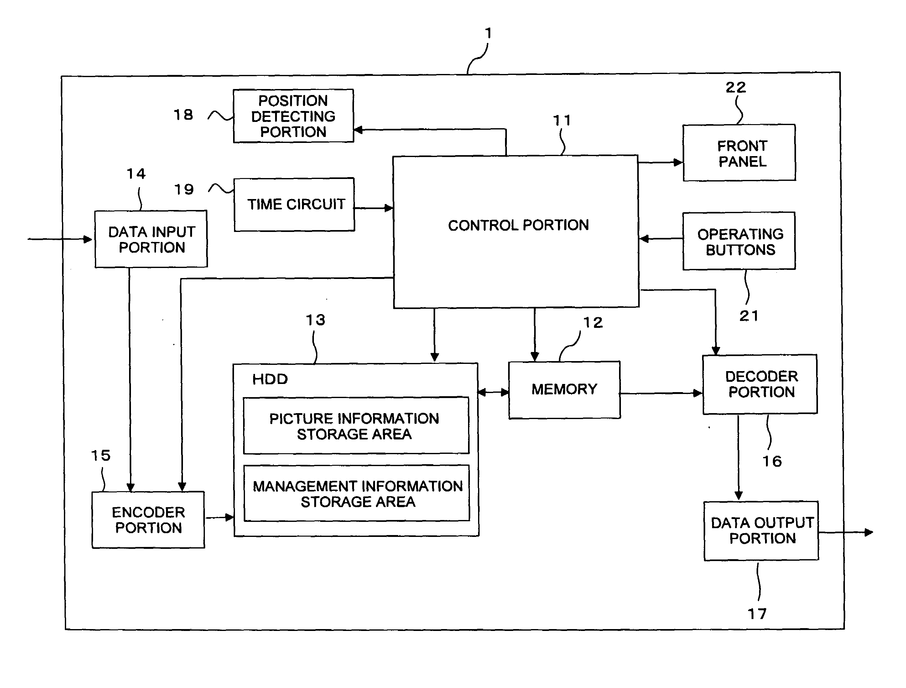
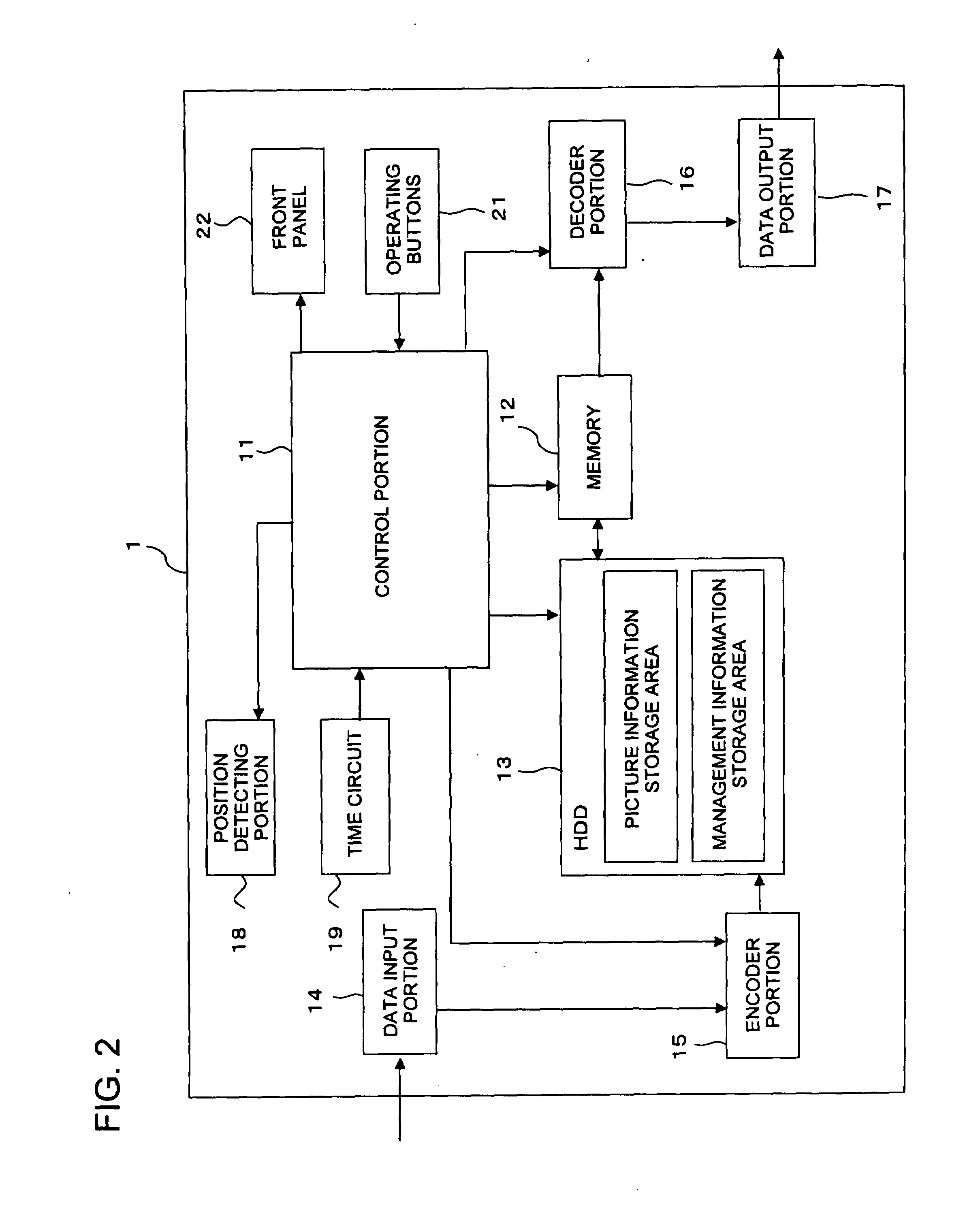
[0030]Here, a structure of a main portion of an electric circuit system of a GPS-equipped HDD recorder 1 in a first embodiment of the present invention will be described with reference to the block diagram shown in FIG. 2.

[0031]As shown in the block diagram of FIG. 2, the GPS-equipped HDD recorder 1 of the present invention is so configured to include at least a control portion 11, a memory 12, an HDD 13, a data input portion 14, an encoder portion 15, a decoder portion 16, a data output portion 17, a position detecting portion 18, a time circuit 19, a set of operating buttons 21, and a front panel 22.

[0032]The control portion 11 is a central processing unit that controls actions of individual members of the GPS-equipped HDD recorder 1 so as to control picture information processing (recording of contents and the like). In addition, the control portion 11 is a brain portion that performs control of individual devices (e.g., the HDD 13 and the like), data calculation, data processing...

second embodiment

[0051]The inside structure of the GPS-equipped HDD recorder in a second embodiment is the same as that in the first embodiment, so description thereof will be omitted.

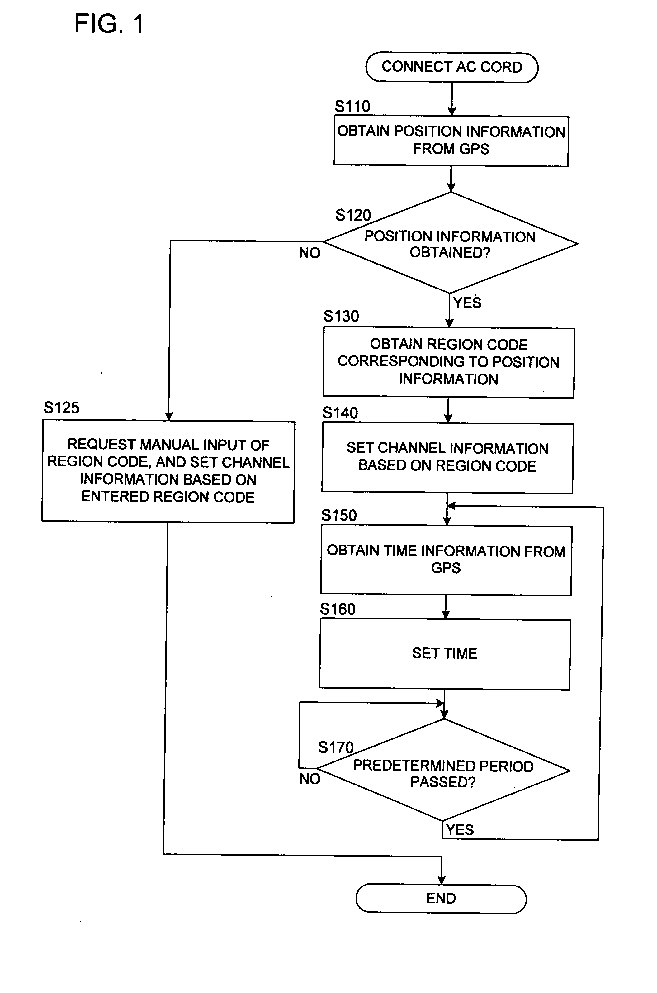
[0052]Here, the channel information setting process in the second embodiment of the present invention will be described with reference to the flowchart shown in FIG. 3 and the block diagram shown in FIG. 2. Note that the steps having the same contents as those in the first embodiment are denoted by the same step numbers, and descriptions thereof will be omitted.

[0053]FIG. 3 is a flowchart showing a process flow of the channel information setting process according to the present invention. As shown in FIG. 3, this process is started when an AC cord (not shown) of the GPS-equipped HDD recorder 1 is connected to an external power source (e.g., an outlet of a commercial power source at home) so that the GPS-equipped HDD recorder 1 is powered on.

[0054]Step S110, step S120 and step S125 are the same as those in the first emb...


PUM


Abstract

When a recording device is connected to a power source and a main power is supplied, position information of the recording device is obtained by using GPS satellites. A region where the recording device is installed is decided based on the obtained position information. Channel information appropriate for the decided region is read out from a storage medium such as a memory, and a tuner of the recording device is set automatically using the read channel information thus read. Additionally, when the position information is obtained, it is decided whether or not the position where the recording device is installed is within a predetermined distance from a boundary between regions. If it is adjacent to other region, a plurality of region codes are read out, and a request for selecting one to perform the channel setting is displayed using a display panel or an OSD function so that the selection can be received.

Description

[0001]This application is based on Japanese Patent Application No. 2006-205737 filed on Jul. 28, 2006, the contents of which are hereby incorporated by reference.BACKGROUND OF THE INVENTION[0002]1. Field of the Invention[0003]The present invention relates to a recording device that can record picture information. In particular, the present invention relates to a recording device equipped with a GPS function for obtaining information of a position where the recording device is installed by using a global positioning system (GPS).[0004]2. Description of Related Art[0005]Recently, digital recording devices such as a DVD (Digital Versatile Disc) recorder or an HDD (Hard Disk Drive) recorder have become widely available as a device for recording pictures and sounds that are processed in an image processing apparatus such as a television set. Many of the recording devices are usually equipped with a tuner for receiving television broadcasting or the like.[0006]Since available broadcasting...

Claims


Application Information

Patent Timeline
Patent Type & Authority Applications(United States)
IPC IPC(8): H04N5/91H04N5/44H04N5/765H04N5/781H04N7/173
CPCH04N5/50H04N21/4524H04N21/4345
Inventor TOJI, SHIGERU
Owner FUNAI ELECTRIC CO LTD
Why Eureka
Try Eureka