Marine reduction and reverse gear unit

a technology of reverse gear unit and engine, which is applied in the direction of marine propulsion, vessel parts, vessel construction, etc., can solve the problems of insufficient torque produced by the engine rotating at about 2200 rpm, and achieve the effect of stable boat speed and enhanced acceleration performan

Active Publication Date: 2008-01-31
YANMAR POWER TECHNOLOGY CO LTD
View PDF8 Cites 27 Cited by
  • Summary
  • Abstract
  • Description
  • Claims
  • Application Information

AI Technical Summary

Benefits of technology

[0009]The present invention provides a marine reduction and reverse gear unit which increases the number of ...

Problems solved by technology

The number of gasoline engine revolutions to produce maximum torque is usually at least...

Method used


Image

  • Marine reduction and reverse gear unit
  • Marine reduction and reverse gear unit
  • Marine reduction and reverse gear unit

Examples


first embodiment

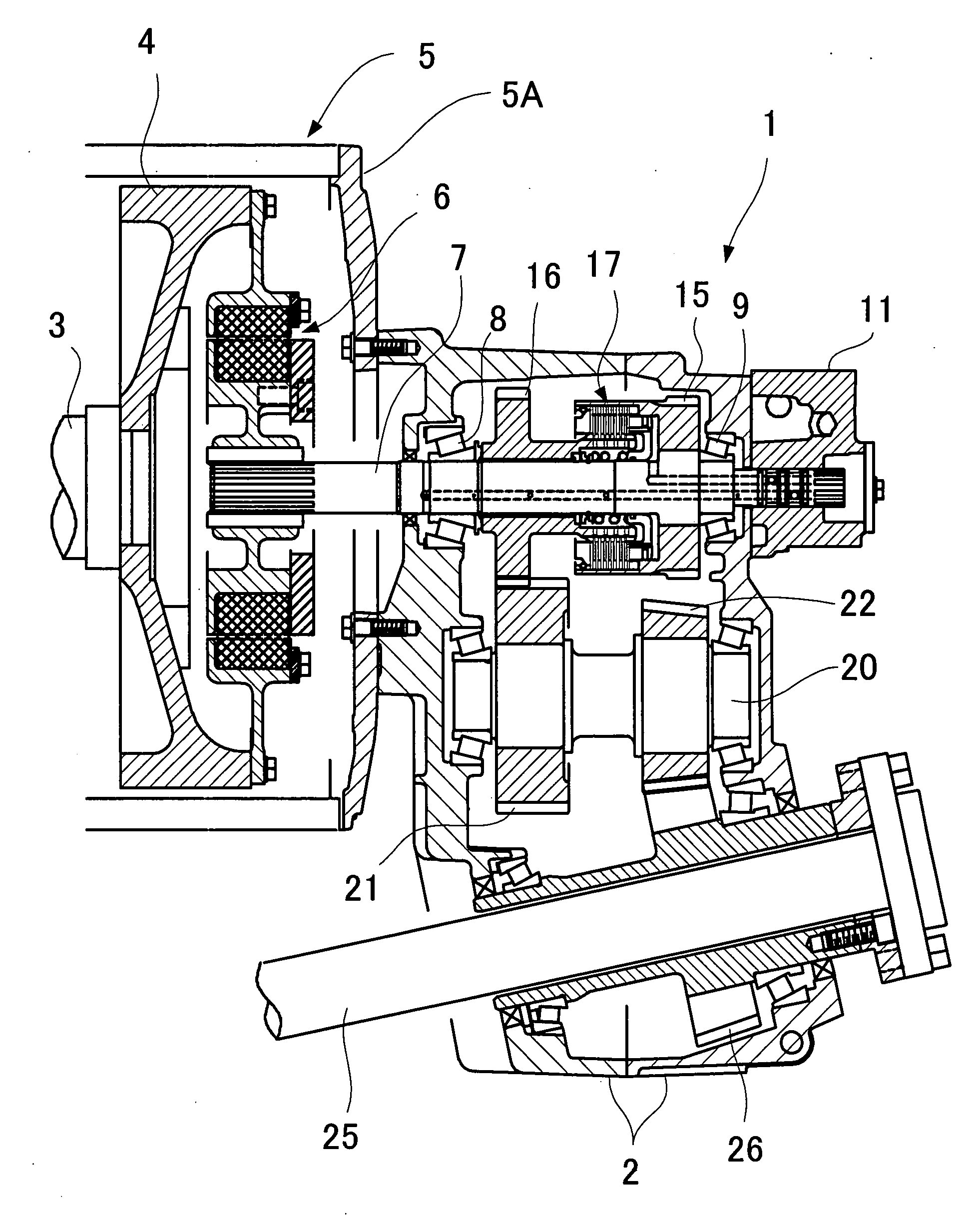
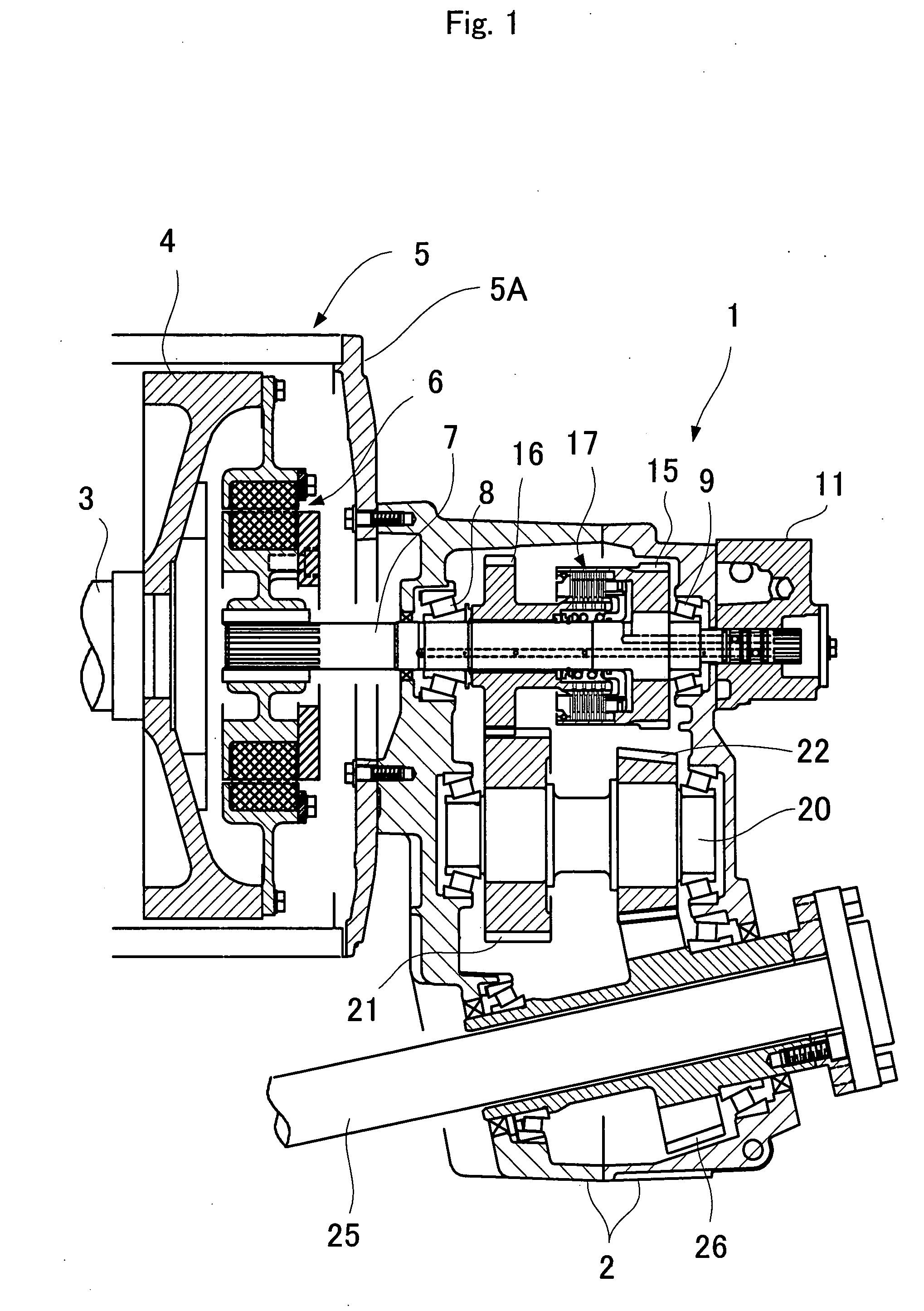
[0034]First, a marine reduction and reverse gear unit according to the present invention is described with reference to FIGS. 1 to 4. FIG. 1 is a longitudinal sectional view illustrating the marine reduction and reverse gear unit. FIG. 2 is a front view illustrating the engagement of gears of the marine reduction and reverse gear unit. FIG. 3 is a sectional view taken along the line III-III of FIG. 2. FIG. 4 is a diagram of a hydraulic circuit provided in the marine reduction and reverse gear unit.

[0035]The marine reduction and reverse gear unit 1 is provided with a casing 2. The casing 2 is fixed on a housing 5 in which components such as a flywheel 4 connected to a rotary shaft 3 of an engine E (FIG. 4) are accommodated. The flywheel 4 is connected to one end of an input shaft 7 via an elastic coupling 6. The input shaft 7 is rotatably supported by bearings 8, 9 in the casing 2. A cover 5A of the housing 5 may be integrally formed with the casing 2.

[0036]A drive gear 15 is fixed o...

second embodiment

[0056]Since the hydraulic circuit operates in the above-described manner, the following effects can be achieved. When wakeboarding, where the boat runs at a comparatively low speed with added ballast water to increase the tare weight, the number of engine revolutions is increased to automatically engage the first forward speed hydraulic clutch 37 and make a high torque range available, thereby providing a stable boat speed and enhanced acceleration performance. When not wakeboarding, where the boat runs at a normal speed, the number of engine revolutions is reduced to automatically disengage the first forward speed hydraulic clutch 37 and engage the second forward speed hydraulic clutch 34, thereby achieving stable running. Thus the operator is free from the need to perform complicated clutch shift operations, and does not have to be conscious thereof when running the boat.

[0057]Next, a third embodiment of a hydraulic circuit is described with reference to FIG. 6. The third embodim...

third embodiment

[0061]According to the hydraulic circuit having the above configuration, when the shift control valve 46b is in the center position at the time of shifting from forward first speed to second forward speed, hydraulic oil is temporarily supplied to both the first forward speed hydraulic clutch 37 and the second forward speed hydraulic clutch 34. As a result, there is no temporal decrease in the number of rotations of the output shaft as indicated by the broken line in the graph of FIG. 7 when shifting from first forward speed to second forward speed, and smooth shifting as indicated by the solid line in the graph of FIG. 7 is achieved partly due to the slip engagement effect of the friction clutch.

[0062]In the embodiment illustrated, the pilot oil passage 57 is provided with a variable throttle valve 58, and the return spring 55 is provided with a spring force adjustment mechanism 55a. However, since these components are to adjust the timing of shifting between first forward speed and...


PUM


Abstract

A marine reduction and reverse gear unit having an output shaft disposed at an acute (or obtuse) angle with respect to an input shaft 7 comprises: a drive gear 15 for transmitting torque from the input shaft 7; first and second driven gears 30, 31 engaged with the drive gear and disposed on the right and left sides thereof to sandwich the drive gear between the first and second driven gears; a reverse gear 16 connected to the drive gear 15 via a reverse hydraulic clutch 16; a first forward speed gear 33 connected to the first driven gear 30 via a hydraulic clutch; a second forward speed gear connected to the second driven gear 31 via a hydraulic clutch; and an output gear 26 fixed on the output shaft and engaged directly with one of the reverse gear 16, first forward speed gear 33 and second forward speed gear 36, or engaged therewith via idle gears to thereby receive the transmitted torque. This marine reduction and reverse gear unit provides a stable boat speed and enhanced acceleration performance by increasing the number of engine revolutions when wakeboarding.

Description

BACKGROUND OF THE INVENTION[0001]1. Field of the Invention[0002]The present invention relates to a marine reduction and reverse gear unit, and particularly to a marine reduction and reverse gear unit suitable for wakeboats.[0003]2. Description of the Related Art[0004]“V-drive” reduction and reverse gear units, which have an output shaft disposed at an acute angle with respect to an input shaft from an engine, are known (for example, Japanese Unexamined Patent Publication No. 2006-117160, Japanese Examined Patent Publication No. 1994-65904, Japanese Utility Model Publication No. 1994-40560, and U.S. Pat. No. 4,383,829). “Angle-drive” reduction and reverse gear units, which have an output shaft disposed at an obtuse angle with respect to an input shaft, are also known (for example, FIG. 4 of Japanese Examined Patent Publication No. 1994-65904, and U.S. Pat. No. 6,443,286).[0005]In V-drive reduction and reverse gear units, the engine is mounted approximately horizontally on the aft sid...

Claims


Application Information

Patent Timeline
IPC IPC(8): B63H23/08
CPCB63H23/08B63H23/30
Inventor OKANISHI, TOSHIAKIHARADA, KAZUYOSHI
Owner YANMAR POWER TECHNOLOGY CO LTD
Why Eureka
Try Eureka