Bending mechanism

a bending mechanism and bending tube technology, applied in the field of bending tubes, can solve the problems of limited diameter, lack of generative force, and difficulty in making a small diameter catheter, and achieve the effects of short bending length, low cost structure, and small diameter

Inactive Publication Date: 2008-01-31
OLYMPUS CORP
View PDF7 Cites 33 Cited by
  • Summary
  • Abstract
  • Description
  • Claims
  • Application Information

AI Technical Summary

Benefits of technology

[0009] The present invention is made in view of the above mentioned circumstances, and an object of the present invention is to provide a bending mechanism with a small diameter and a short bending length, and having a simple and a low cost structure.

Problems solved by technology

In the above mentioned conventional technology, since it is necessary to accommodate the thread member 3 and the shape memory alloy coil which is the shape memory member 10, inside the guide member 5, there are limitations on making a small diameter, and it is difficult to use in a catheter of a small diameter.
However, when a bending length is made short, there is a lack of a generative force in the shape memory alloy coil due to an increase in a distortion with respect to the long object 1, and it is necessary to increase a length of the curved part 2.
Thus, in a conventional method, it has been difficult to realize an active bending mechanism with a small diameter, and a short bending length.

Method used


Image

  • Bending mechanism
  • Bending mechanism
  • Bending mechanism

Examples


first embodiment

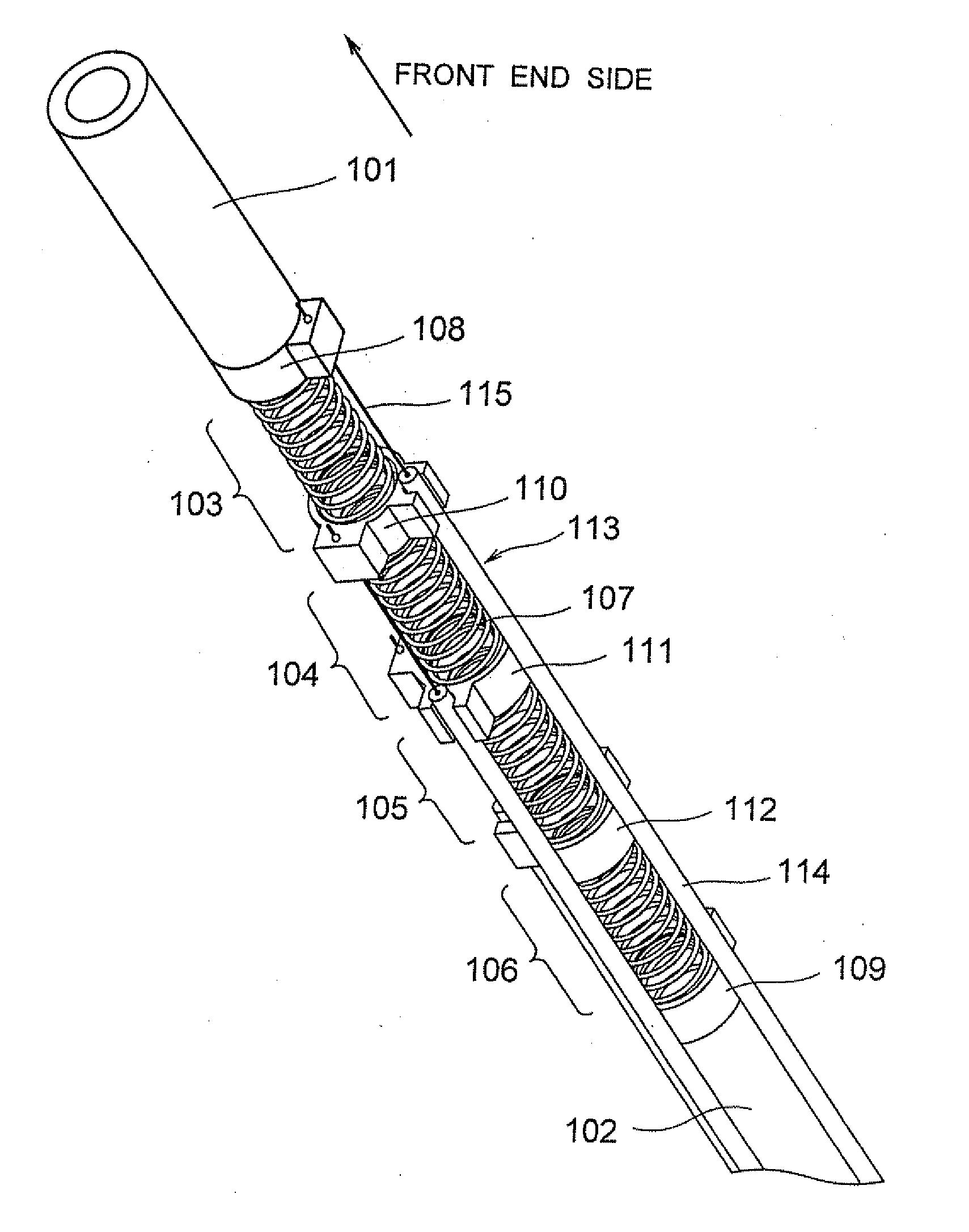
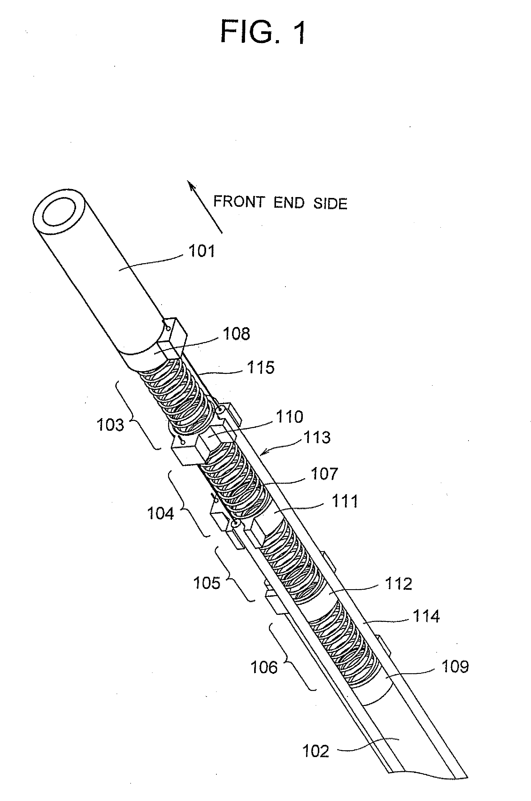
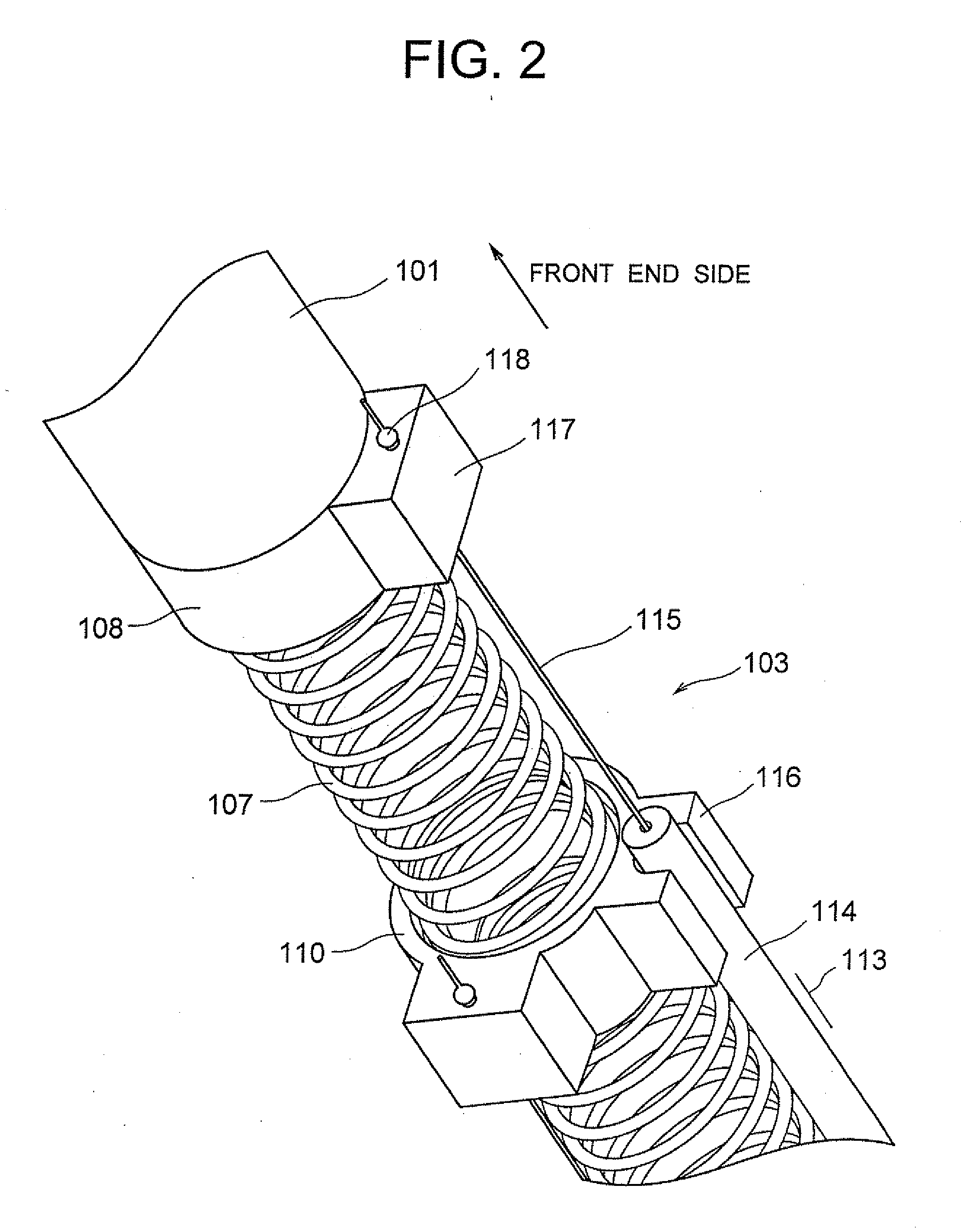
[0026] A first embodiment of the present invention will be described by using FIG. 1 to FIG. 3. FIG. 1 shows a perspective view of a bending mechanism of the first embodiment. A first bending portion 103, a second bending portion 104, a third bending portion 105, and a fourth bending portion 106 are disposed between a front tube 101 and a rear tube 102. The first bending portion 103 to the fourth bending portions 106 are formed by one integrated coiled spring 107. A front link member 108 is disposed toward the front tube 101 of the first bending portion 103, and a rear link member 109 is disposed toward the rear tube 102 of the fourth bending portion 106. A first intermediate link member 110 is disposed between the first bending portion 103 and the second bending portion 104, a second intermediate link member 111 is disposed between the second bending portion 104 and the third bending portion 105, and a third intermediate link member 112 is disposed between the third bending portion...

second embodiment

[0036] A second embodiment of the present invention will be described below by using FIG. 4. An overall structure of a bending mechanism of the second embodiment is similar to the structure of the bending mechanism described in the first embodiment, but a portion shown in FIG. 4 is different. As shown in FIG. 4, a bending portion positioned between a front link member 201 and a rear link portion 202 is formed by a coiled spring 203, and an actuator 204 is disposed at an outer circumference thereof.

[0037] The actuator 204 according to the second embodiment includes a tube member 205, and an SMA wire 206 which is inserted into the tube member 205, and a front end portion of the tube member is fixed at a tube installing portion 208 of the rear link member 202, by adhering etc. Moreover, a front end of the SMA wire 206 is inserted into a through hole which is formed in a protrusion 209 of the front link member 201, and a caulking member 207 is installed at a front side ahead of a throu...

third embodiment

[0041] A third embodiment of the present invention will be described below by using FIG. 5.

[0042] A bending mechanism according to the third embodiment, as shown in FIG. 5, has a coiled spring 303 installed between a front tube 310 and a rear tube 320, which includes a finely spaced portion 303a having a comparatively large number of turns per a unit length in an axial direction (in other words, a comparatively small spring pitch), and a coarsely spaced portion 303b having a comparatively small number of turns per unit length in the axial direction (in other words, a comparatively large spring pitch), arranged alternately, and an actuator 304 is disposed at an outer circumference of the coiled spring 303. It is possible to structure the finely spaced portion 303a such that each winding makes a close contact mutually till a predetermined load is exerted.

[0043] The actuator 304 according to the third embodiment includes a tube member 305, and an SMA wire 306 which is inserted into t...


PUM


Abstract

A first bending portion, a second bending portion, a third bending portion, and a fourth bending portion are formed by a coiled spring. A front link member is disposed toward a front tube of the first bending portion, and a rear link member is disposed toward a rear tube of the fourth bending portion. A first intermediate link member is disposed between the first bending portion and the second bending portion, a second intermediate link member is disposed between the second bending portion and the third bending portion, and a third intermediate link member is disposed between the third bending portion and the fourth bending portion. A first actuator includes a tube member and an SMA wire member, and when a distance between the front link member and the tube member is shortened by driving the first actuator, the first bending portion is bent.

Description

CROSS-REFERENCE TO RELATED APPLICATION [0001] The present application is based upon and claims the benefit of priority from the prior Japanese Patent Application No. 2006-199301 filed on Jul. 21, 2006; the entire contents of which are incorporated herein by reference. BACKGROUND OF THE INVENTION [0002] 1. Field of the Invention [0003] The present invention relates to a bending mechanism, and in particular, to a bending mechanism which has a small diameter, and is capable of shortening a bending length by, such as a bending mechanism which is applicable as a bending mechanism for a medical catheter and an endoscope. [0004] 2. Description of the Related Art [0005] So far, it is usual that a catheter which is used in combination with an endoscope does not have an active bending mechanism. However, in a case of using in a part in which, it is difficult to be inserted, the active bending mechanism may be useful as it improves insertability. Moreover, generally, although a pulling by a wi...

Claims


Application Information

Patent Timeline
Patent Type & Authority Applications(United States)
IPC IPC(8): A61B1/008
CPCA61B1/0058
Inventor YASUNAGA, SHINJI
Owner OLYMPUS CORP
Why Eureka
Try Eureka