
Flat Screen TV Bracket For A Vehicle

Inactive Publication Date: 2008-02-07
KO KOBER CORP
View PDF30 Cites 61 Cited by
  • Summary
  • Abstract
  • Description
  • Claims
  • Application Information

AI Technical Summary

Benefits of technology

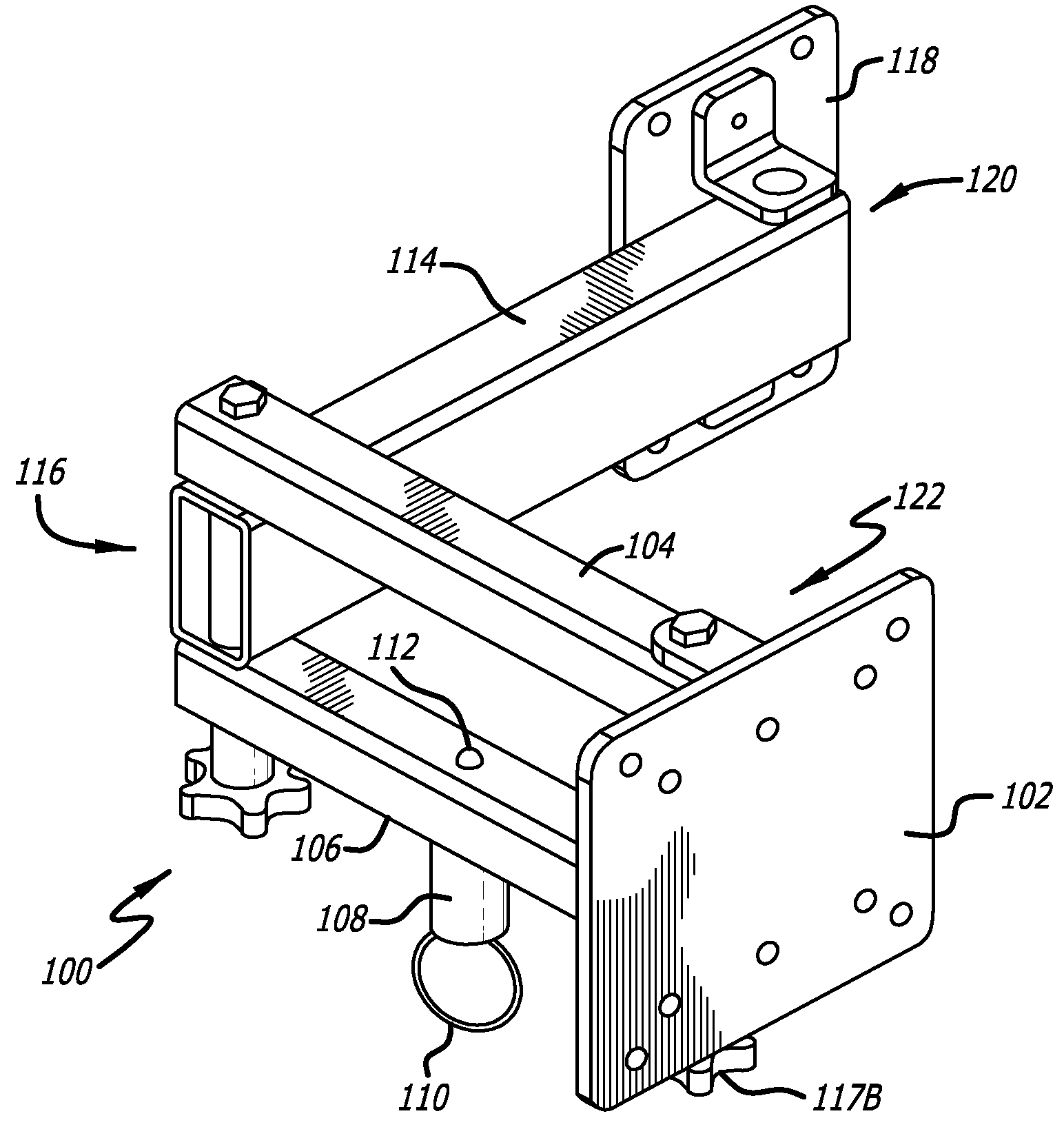
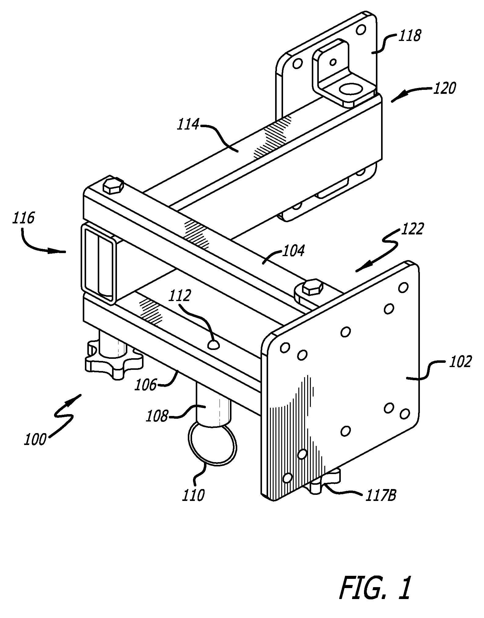
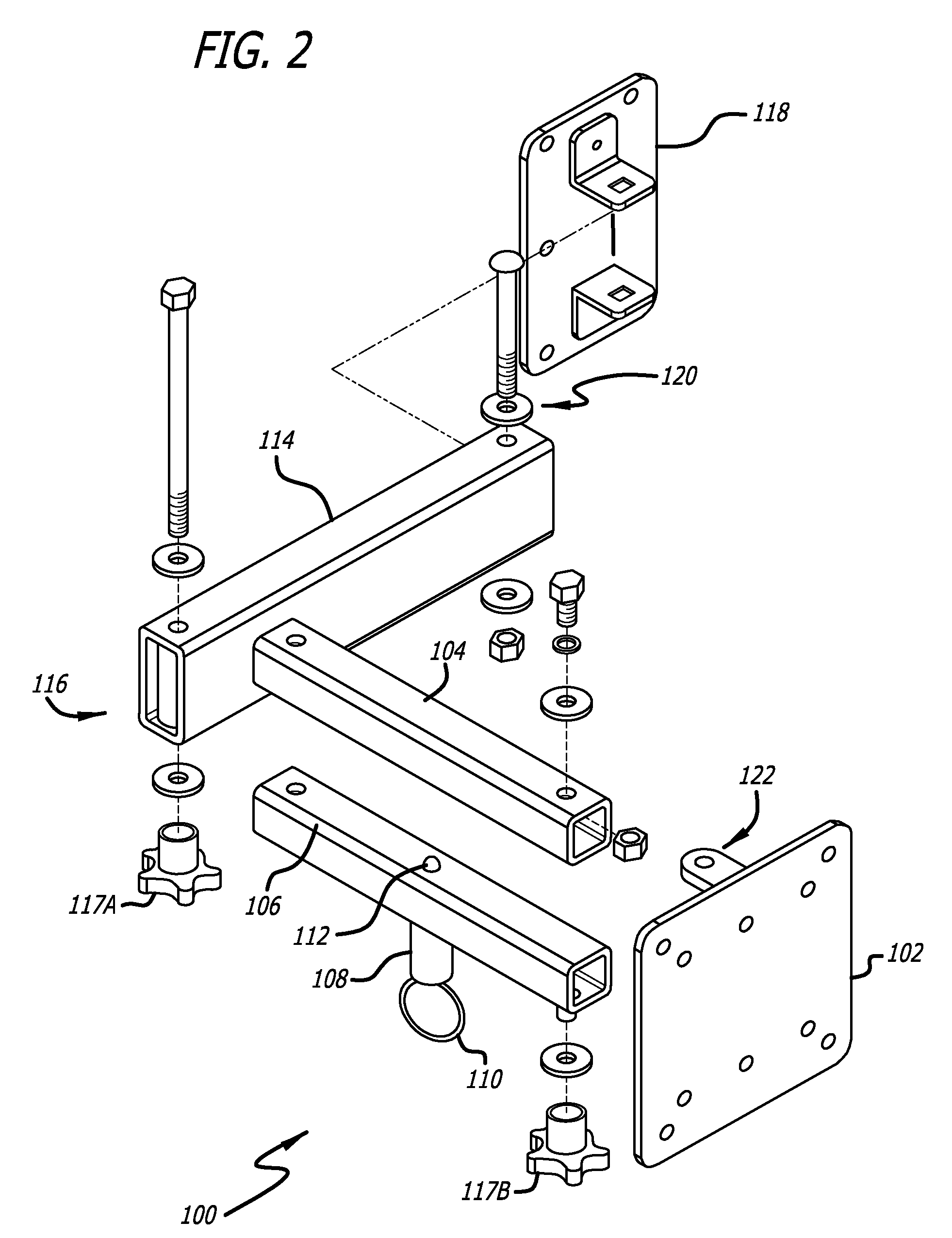
[0008]In one preferred embodiment according to the present invention, a mounting bracket is described for a thin profile media display. The mounting bracket includes a wall mounting plate which supports a pivotable, jointed arm. The jointed arm is ultimately connected to a display mounting plate that connects to a display (e.g., an LCD TV). The jointed arm can be selectively locked in place with user adjustable knobs that rotate on a joint-forming pin to create or relieve pressure against the arm. Further, the arm includes a spring biased locking pin that locks the bracket into a folded or retracted position. In this respect, the locking or position retaining mechanisms of the bracket allow a user to not only reposition a display, but maintain the position of the display during travel.

Problems solved by technology

While these brackets are ideal for home use, they are less than desirable for use in RV's, trailers, boats, airplanes and other vehicles.

Method used


Image

  • Flat Screen TV Bracket For A Vehicle
  • Flat Screen TV Bracket For A Vehicle
  • Flat Screen TV Bracket For A Vehicle

Examples


Embodiment Construction

[0032]FIGS. 1-4 illustrate a preferred embodiment according to the present invention of a bracket 100 for a thin media display screen such as an LCD television. Unlike many prior brackets, the present bracket 100 includes multiple locking mechanisms to secure the bracket 100 and thus the media display screen in various positions. Thus, the present invention is especially suitable for moving vehicles such as RVs, cars, trucks, boats and planes where a media display is subject to movement, jarring and other forces.

[0033]Wall mounting plate 118 is mounted to a wall or similar surface to secure the bracket 100 in place. The bracket 100 includes a first arm 114 connected to the wall mounting plate 118 by joint 120. The opposite end of the first arm 114 connects via joint 116 to the third arm 104 and fourth arm 106. The third and fourth arms 104 and 106 in turn connect via hinge 122 to the media screen mounting plate 102.

[0034]Preferably, the media screen mounting plate 102, as well as th...


PUM


Abstract

In one preferred embodiment, a mounting bracket is described for a thin profile media display. The mounting bracket includes a wall mounting plate which supports a pivotable, jointed arm that is connected to a a display (e.g., an LCD TV). The jointed arm can be selectively locked in place with user adjustable knobs that rotate on a joint-forming pin to lock or unlock the joint from movement. Further, the arm includes a spring biased locking pin that locks the bracket into a folded or retracted position. In this respect, the position retaining mechanisms of the bracket for repositioning of a display, as well as maintain the position of the display during travel.

Description

RELATED APPLICATIONS[0001]This application claims priority to U.S. Provisional Application Ser. No. 60 / 821,105 filed Aug. 1, 2006 entitled Flat Screen TV Bracket For A Vehicle which is hereby incorporated by reference.BACKGROUND OF THE INVENTION[0002]Thin profile media displays such as televisions or computer monitors utilizing LCD or plasma technologies for example, are becoming increasingly common as prices fall for manufacturing this technology. Due to the thin nature of these screens, mounting brackets have become a particularly desirable method of fixing these media screens to the walls and other structures within the home.[0003]Examples of such mounting brackets include U.S. Application Number 2005 / 0087661, 2004 / 0045224, 2003 / 0080268 and 2002 / 0079415; the contents of which are hereby incorporated by reference.[0004]While these brackets are ideal for home use, they are less than desirable for use in RV's, trailers, boats, airplanes and other vehicles.SUMMARY AND OBJECTS OF THE ...

Claims


Application Information

Patent Timeline
IPC IPC(8): A47F5/00
CPCB60R11/0229B60R2011/0052B60R2011/0082B60R2011/0084B60R2011/0089B60R2011/0005F16M11/08F16M11/2014F16M13/02F16M2200/022F16M2200/065F16M11/04
Inventor OLAH, TIBORPERVORSE, JOHNDEPARTE, CHRIS
Owner KO KOBER CORP
Learn More