Smart Ethernet edge networking system

a networking system and edge technology, applied in data switching networks, instruments, frequency-division multiplexes, etc., can solve the problems of increasing the workload of users, and reducing the service life of users

Active Publication Date: 2008-02-07
CIENA
View PDF49 Cites 57 Cited by
  • Summary
  • Abstract
  • Description
  • Claims
  • Application Information

AI Technical Summary

Benefits of technology

[0012]One embodiment provides a telecommunications system comprising a network for transporting packets on a path between selected subscriber end points. The network has multiple nodes connected by links, with each node (a) pairing the forward and backward paths of a connection and (b) allowing for the injection of me...

Problems solved by technology

Existing network elements which offer network access using Ethernet technology are not designed to make maximum use of the legacy network links existing at the edge of the carrier networks.
The edge of the network is quickly becoming a bottleneck as the new applications are becoming more and more demanding for bandwidth.
It is therefore impossible for a carrier to use operation administration and maintenance (OAM) packets, in order to create loopbacks within the connection path to troubleshoot a connection without setting up out-of-service explicit paths.
One issue with all these existing protection protocols is that they do not take into account business policies, such as desired level of protection, for determin...

Method used


Image

  • Smart Ethernet edge networking system
  • Smart Ethernet edge networking system
  • Smart Ethernet edge networking system

Examples


Embodiment Construction

Path Association

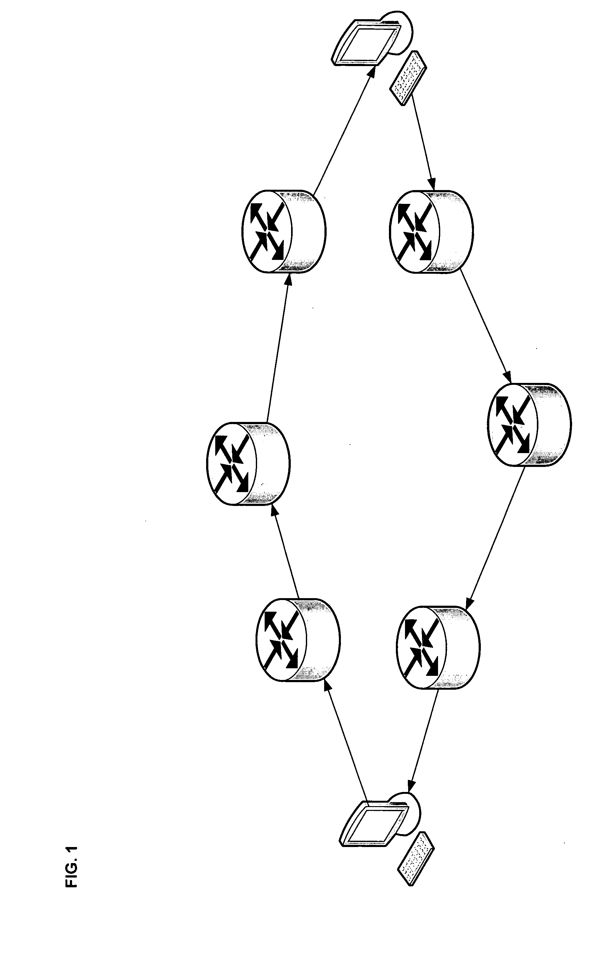
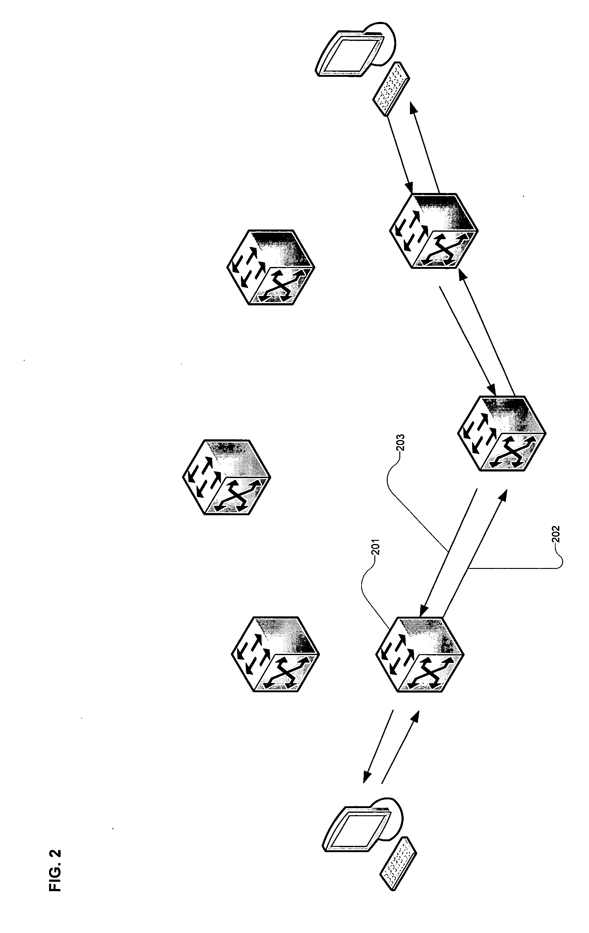
[0024]Given the ability of the VMS to ensure that each direction of the connection uses the same path (as per FIG. 2), each network element (e.g. WiMAX switch) is able to (1) pair each forward 202 and backward 203 path of a connection at each node in the path of a connection and (2) allow for injection of messages in the backward direction of a connection from any node in the path. This capability, depicted in FIG. 3, is referred to herein as creating a “hairpin”303. The knowledge of the pairs at each node 201 allows creating loopbacks, and then using control packets at any point in a connection in order to perform troubleshooting. Loopbacks can also be created by the VMS or manually generated. The pairing is possible in this case because the VMS ensures that both paths of the connections (forward and backward) take the same route which is not currently the case for Ethernet

[0025]Other examples of uses for this path association could be where two uni-directional path...


PUM


Abstract

A telecommunications system includes a network for transporting packets on a path between selected subscriber end points. The network has multiple nodes connected by links, with each node (a) pairing the forward and backward paths of a connection and (b) allowing for the injection of messages in the backward direction of a connection from any node in the path without needing to consult a higher OSI layer. A system is also provided for protecting connection paths for transporting data packets through an Ethernet telecommunications network having a multiplicity of nodes interconnected by a multiplicity of links. Primary and backup paths are provided through the network for each of multiple connections, with each path including multiple links. Data packets arriving at a first node common to the primary and backup paths are duplicated, and one of the duplicate packets is transported over the primary path, the other duplicate packet is transported over the backup path, and the duplicate packets are recombined at a second node common to the primary and backup paths.

Description

FIELD OF THE INVENTION[0001]The present invention generally relates to Ethernet access and, in particular, to bandwidth efficient Ethernet grid networking systems.BACKGROUND OF THE INVENTION[0002]Ethernet is rapidly becoming the protocol of choice for consumer, enterprise and carrier networks. It is expected that most networks will evolve such that Ethernet will be the technology used to transport all the multimedia applications including, for example, triple-play, fixed-mobile-convergence (FMC), and IP multimedia sub-systems (IMS). Existing network elements which offer network access using Ethernet technology are not designed to make maximum use of the legacy network links existing at the edge of the carrier networks. The edge of the network is quickly becoming a bottleneck as the new applications are becoming more and more demanding for bandwidth.[0003]Telecommunications carriers are constantly looking for new revenue sources. They need to be able to deploy rapidly a wide ranging ...

Claims


Application Information

Patent Timeline
IPC IPC(8): H04J3/14
CPCH04L12/66
Inventor ARSENEAULT, JIMBARRETT, CHRISFRANK, PABLOSMITH, BRIAN
Owner CIENA
Why Eureka
Try Eureka