Wireless telecommunication apparatus and wireless telecommunication method

a telecommunication apparatus and wireless technology, applied in the field of wireless telecommunication equipment, can solve the problems of increasing the power consumption of a mobile station with increased transmission speed, increasing the number of demodulations in a certain length of time, and suppressing the power consumption of the terminal apparatus, so as to increase the transmission speed, the effect of increasing the transmission speed and increasing the transmission speed

Inactive Publication Date: 2008-02-07
FUJITSU LTD
View PDF12 Cites 5 Cited by
  • Summary
  • Abstract
  • Description
  • Claims
  • Application Information

AI Technical Summary

Benefits of technology

[0016]The terminal apparatus may comprise a diversity reception in which a part of the operation of a reception antenna is stopped in the terminal apparatus during a time period indicated by the scheduling information, thereby stopping a process for receiving data. As in the case of stopping a demodulation circuit or other such circuit, the power consumption of the terminal apparatus can be suppressed.
[0017]The terminal apparatus may be configured to perform an automatic gain control during a time period indicated by the scheduling information. Alternately, the terminal apparatus may be configured to perform a search for carrying out a handover from one frequency to another during a time period indicated by the scheduling information. The time period indicated by the scheduling information is a frame allocated to another station, and therefore the problem of having a degradation of communication characteristic does not occur even if automatic gain control is actively performed. Also, the active carrying out of a search during a time period indicated by scheduling information makes it possible to solve the problem, associated with an increase in transmission speed, of being unable to secure the time for a search.
[0018]The present invention is contrived to utilize a result of a scheduling process at a base station that allocates resources to each mobile terminal apparatus and to notify, via a control channel, individual mobile stations of the timing for the next transmission of data. Referring to the information unattached to the control channel, the mobile station stops the operation of a circuit that does not need to be operating for a frame with which data addressed to the apparatus itself is not transmitted during a predetermined time period, performs automatic gain control actively, and carries out a search for a handover from one frequency to another. This configuration enables the improvement of various problems occurring in association with an increased transmission speed.

Problems solved by technology

This in turn causes the power consumption for an overall process including the FFT process to increase with transmission speed.
One factor that causes increased power consumption of a mobile station with increased transmission speed is an increased number of demodulations in a certain length of time.
The power consumption in a demodulation circuit such as the FFT may increase, but there is a limitation in the capacity of the battery of a mobile station.
As for a mobile station equipped with a diversity reception for improving reception performance, there is a similar problem with the length of time in which the station is able to communicate decreasing with the number of reception systems in operation because of an increased power consumption in proportion with the aforementioned number.
Furthermore, as a result of a shortened demodulation interval that is associated with an increased transmission speed, the establishment of timing becomes difficult, in particular for a mobile station, when receiving data to carry out a peripheral search when a handover is performed from one frequency to another, and therefore the system becomes less convenient to use.
This causes a characteristic of the received signal to be degraded and brings about the problem of a drastic reduction in throughput.

Method used


Image

  • Wireless telecommunication apparatus and wireless telecommunication method
  • Wireless telecommunication apparatus and wireless telecommunication method
  • Wireless telecommunication apparatus and wireless telecommunication method

Examples


Embodiment Construction

[0033]The following is a detailed description of the preferred embodiment of the present invention, referring to the accompanying drawings.

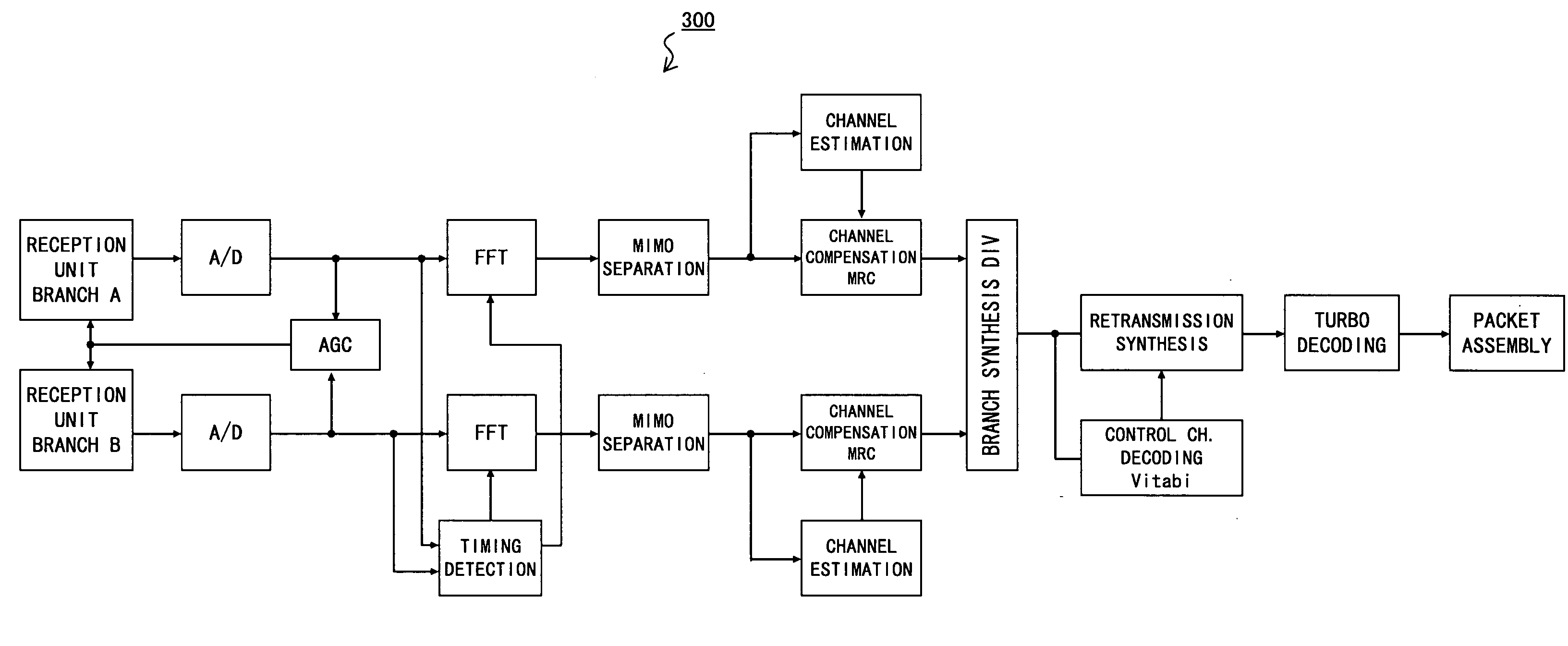
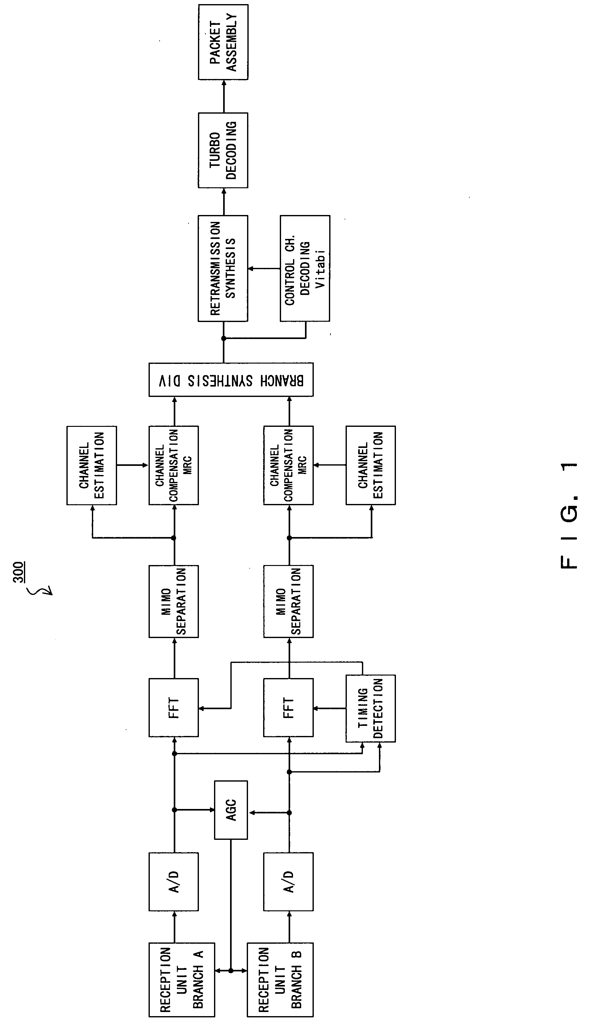
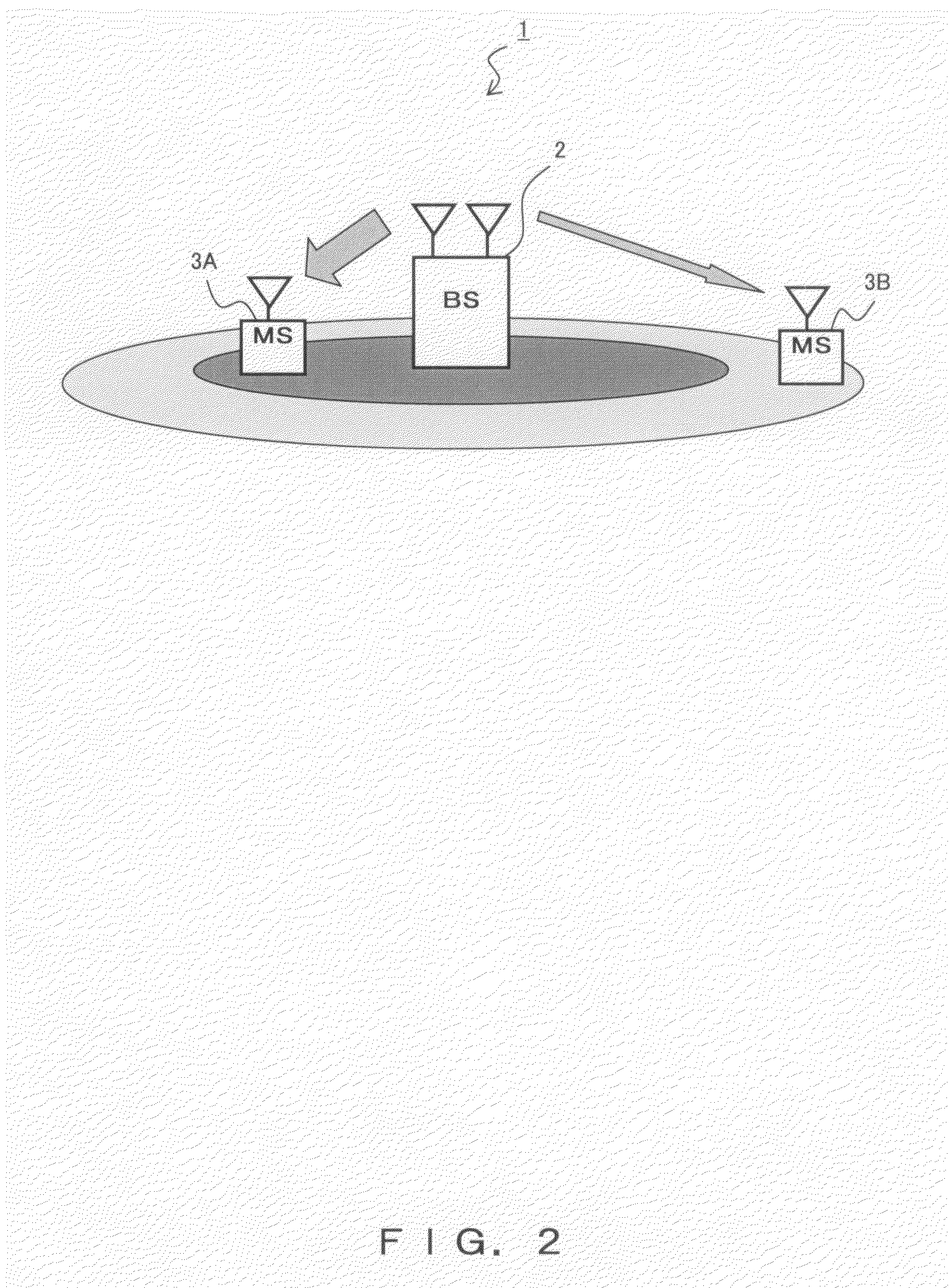
[0034]FIG. 2 is a configuration diagram of a wireless telecommunication (“wireless telecom” hereinafter) system 1 according the present embodiment. The wireless telecom system 1 employing the TDMA system comprises a base station (BS) 2 and mobile stations (MSs or mobile terminals—abbreviated as “terminal” hereinafter) 3. FIG. 1 only shows one base station 2 and two terminals 3A and 3B as being under the management of the base station 2 in order to simplify the configuration.

[0035]The wireless telecom system 1 employing the TDMA system, e.g., a cellular system of the 3.5 generation and thereafter, is configured to be applicable to many transmission resources, that is, frames are configured to be applicable a terminal 3 having good reception quality, for the purpose of increasing the sector throughput. The terminal 3 with many transmission resource...


PUM


Abstract

In a wireless telecommunication system employing a time division multiple access (TDMA) system, a scheduler of a base station determines an allocation of a first frame and a second frame for a first data set to be transmitted to a terminal and a second data set to be transmitted thereto after the first data set. A generation unit generates scheduling information for notifying the terminal of the timing of transmitting the second data set on the basis of a relative number of frames for indicating the number of second frames relative to that of the first frame. An addition unit adds scheduling information generated by the generation unit to a control channel corresponding to the first data set and sends the result to the terminal.

Description

BACKGROUND OF THE INVENTION[0001]1. Field of the Invention[0002]The present invention relates to a wireless telecommunication technique adopting a Time Division Multiple Access (TDMA) system and in particular to a technique for stopping a reception circuit of a terminal apparatus in between frames transmitted to a station other than the terminal apparatus itself.[0003]2. Description of the Related Art[0004]TDMA is used for telecommunication standards such as High-Speed Downlink Packet Access (HSDPA), Worldwide Interoperability for Microwave Access (WiMAX), and super 3G and 4G, all of which are expected to be more popular in the future. A TDMA transmission system is capable of implementing dedicated channels by a plurality of mobile stations (MSs) receiving downlink access channels from a base station (BS) in units of frames in a time division and adjusting transmission speed by increasing or decreasing the number of transmission frames. The TDMA system is also considered to be an im...

Claims


Application Information

Patent Timeline
Patent Type & Authority Applications(United States)
IPC IPC(8): H04B7/212H04B7/04H04B7/08H04J3/00H04J11/00H04J99/00H04W16/02H04W16/28H04W52/02H04W72/12
CPCH04W72/1289H04W52/0219H04W52/0216Y02D30/70H04W72/23
Inventor SHIMIZU, HIROTOSHI
Owner FUJITSU LTD
Why Eureka
Try Eureka