Method for manufacturing an optical fiber preform

a manufacturing method and optical fiber technology, applied in glass making apparatus, applications, instruments, etc., can solve the problems of low ratio between the outer radius of the tube and the radius of the central core, the method is not very productive, and the fundamental mode is not completely guided and shows additional losses

Active Publication Date: 2008-02-07
DRAKA COMTEQ BV
View PDF7 Cites 39 Cited by
  • Summary
  • Abstract
  • Description
  • Claims
  • Application Information

AI Technical Summary

Benefits of technology

[0036] According to one embodiment, for a wavelength of about 1550 nm, the optical fiber has losses of about 0.18 dB / km or less.

Problems solved by technology

In the above-described structure, with an outer cladding having substantially the same refractive index as the central core, the fundamental mode is not completely guided and shows additional losses, called leakage.
In this context, either the ratio between the outer radius of the primary preform and the radius of the central core is relatively high and the quantity of silica to be deposited inside the tube is high, in which case the primary preform is costly and the method is not very productive; or the ratio between the outer radius of the tube and the radius of the central core is relatively low and the optical fiber obtained by drawing from the final preform does not have good properties and its attenuation is substantially higher.
Nonetheless the fluorine-doped silica particles are synthetic particles which are much more expensive than natural silica particles.

Method used


Image

  • Method for manufacturing an optical fiber preform
  • Method for manufacturing an optical fiber preform
  • Method for manufacturing an optical fiber preform

Examples


Embodiment Construction

[0041] The present invention now will be described more fully hereinafter in the following detailed description of the invention, in which some, but not all embodiments of the invention are described. Indeed, this invention may be embodied in many different forms and should not be construed as limited to the embodiments set forth herein; rather, these embodiments are provided so that this disclosure will satisfy applicable legal requirements.

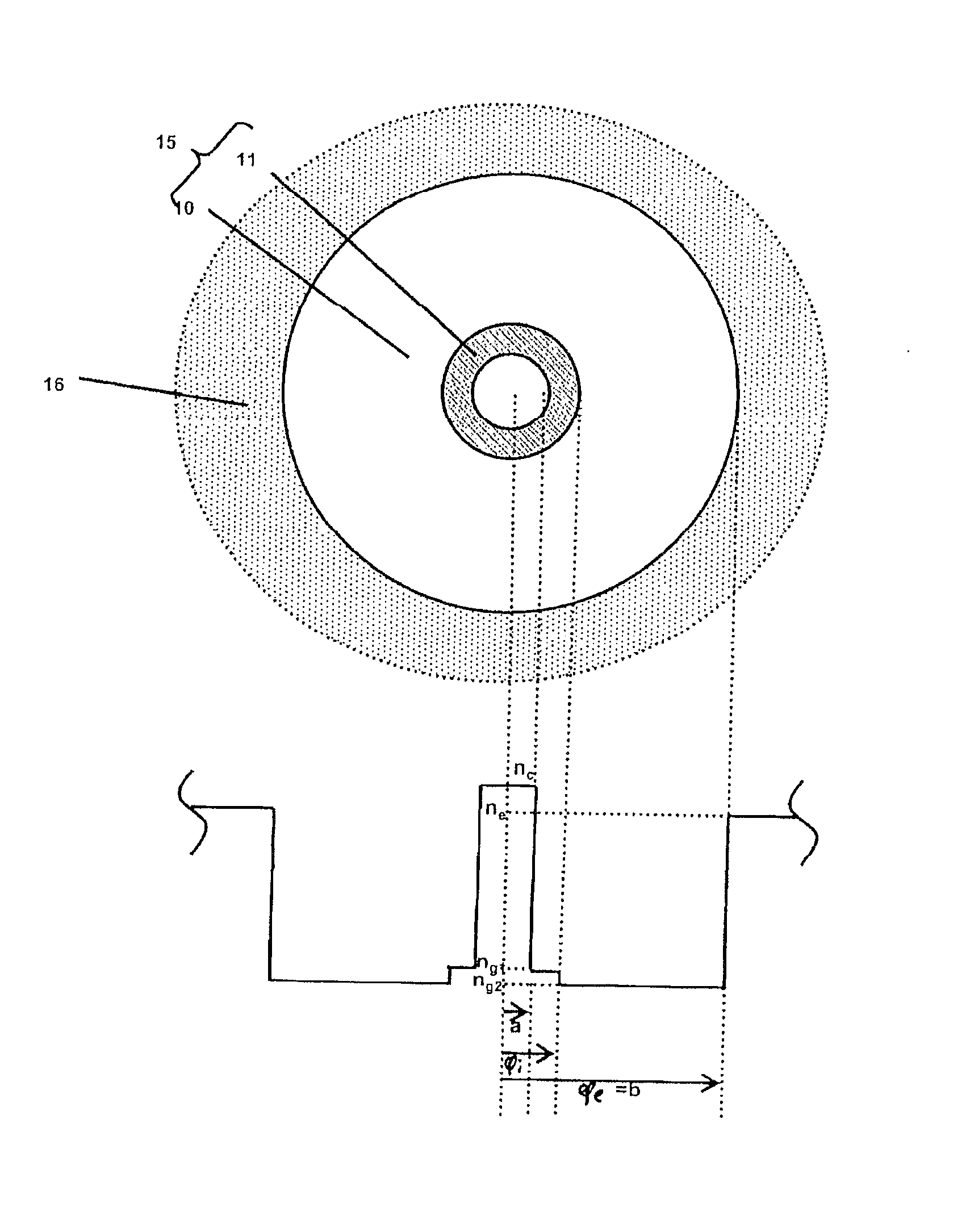
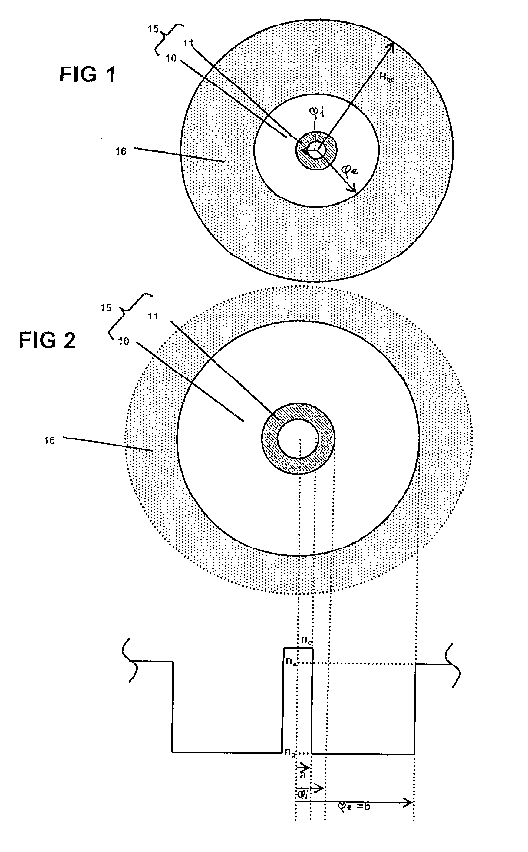
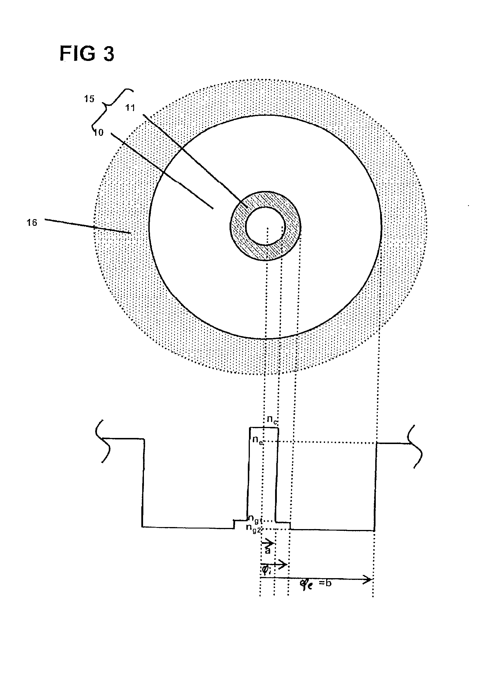
[0042] The invention proposes a method for fabricating an optical fiber preform.

[0043] A primary preform is made from a thick tube in silica doped with fluorine. As used herein the term “thick tube” refers to a tube having a large wall thickness. The cross-section area of the tube is maximally (no more than) about 15%, for example maximally about 10%, less than the total cross section area of the primary preform, i.e. a large part of the inner cladding (the second part of the inner cladding) of the primary preform consists of the thick tube do...


PUM

PropertyMeasurementUnit
areaaaaaaaaaaa
areaaaaaaaaaaa
areaaaaaaaaaaa

Abstract

A method for manufacturing a final optical fiber preform via overcladding of a primary preform having a cross section area is disclosed. The method includes at least one manufacturing step of the primary preform by deposit of an inner cladding and of a central core inside a tube of fluorine-doped silica, the tube being chosen such that it has a cross section area that is maximally about 15% less than the cross section area of the primary preform. With the method of the invention it is possible to manufacture a preform of large capacity at reduced cost which allows the drawing of an optical fiber having reduced transmission losses.

Description

FIELD OF THE INVENTION [0001] The present invention relates to a method for manufacturing an optical fiber preform. BACKGROUND OF THE INVENTION [0002] An optical fiber is made by drawing a preform on a drawing tower. A preform for example comprises a primary preform consisting of a very high quality glass tube, part of the cladding and the core of the fiber. This primary preform is then overcladded or sleeved to increase its diameter and to form a preform which can be used on a drawing tower. In this context, the term inner cladding is used for the cladding formed inside the tube, and outer cladding for the cladding formed on the outside of the tube. The homothetic fiber drawing operation consists of placing the preform vertically in a tower and drawing a fiber strand from one end of the preform. For this purpose a high temperature is applied locally to one end of the preform until the silica is softened, the fiber drawing speed and temperature then being permanently controlled duri...

Claims


Application Information

Patent Timeline
Patent Type & Authority Applications(United States)
IPC IPC(8): C03B37/075G02B6/036
CPCC03B37/01291C03B37/01892C03B2201/02C03B2201/12C03B2201/31C03B2203/22G02B6/0365C03B2203/24C03C13/045C03C13/046C03C17/3417G02B6/03627C03B2203/23
Inventor GONNET, CEDRICREGNIER, ELISEGOOIJER, FRANSNOUCHI, PASCALE
Owner DRAKA COMTEQ BV
Why Eureka
Try Eureka