Optical fiber and method of making the same

a technology of optical fiber and optical fiber, applied in the field of optical fiber, can solve the problems of inability to obtain reliable transmission loss reducing effect, inability to fully realize the reduction of transmission loss in optical fiber, and inability to realize the reduction of transmission loss

Inactive Publication Date: 2002-04-18
SUMITOMO ELECTRIC IND LTD
View PDF0 Cites 51 Cited by
  • Summary
  • Abstract
  • Description
  • Claims
  • Application Information

AI Technical Summary

Problems solved by technology

In the transmission of light using an optical fiber, the transmission loss (Rayleigh scattering loss) caused by Rayleigh scattering within the optical fiber becomes problematic.
However, conventionally proposed manufacturing methods which are effective in lowering Rayleigh scattering loss, such as the above-mentioned manufacturing method having an annealing process using a heating furnace, and the like are not considered to fully realize the reduction of transmission loss in the optical fiber.
In particular, there has been a problem that even optical fibers prepared by the same manufacturing method yield a case where the transmission loss reducing effect is obtained and a case where the transmission loss is hardly reduced or increases to the contrary, whereby the transmission loss reducing effect cannot be obtained reliably.
Here, the dependence of transmission loss upon tension i

Method used


Image

  • Optical fiber and method of making the same
  • Optical fiber and method of making the same
  • Optical fiber and method of making the same

Examples


first embodiment

[0125] The configuration of the optical fiber will now be explained. FIG. 7 is a chart showing the refractive index profile of the second optical fiber in accordance with the present invention.

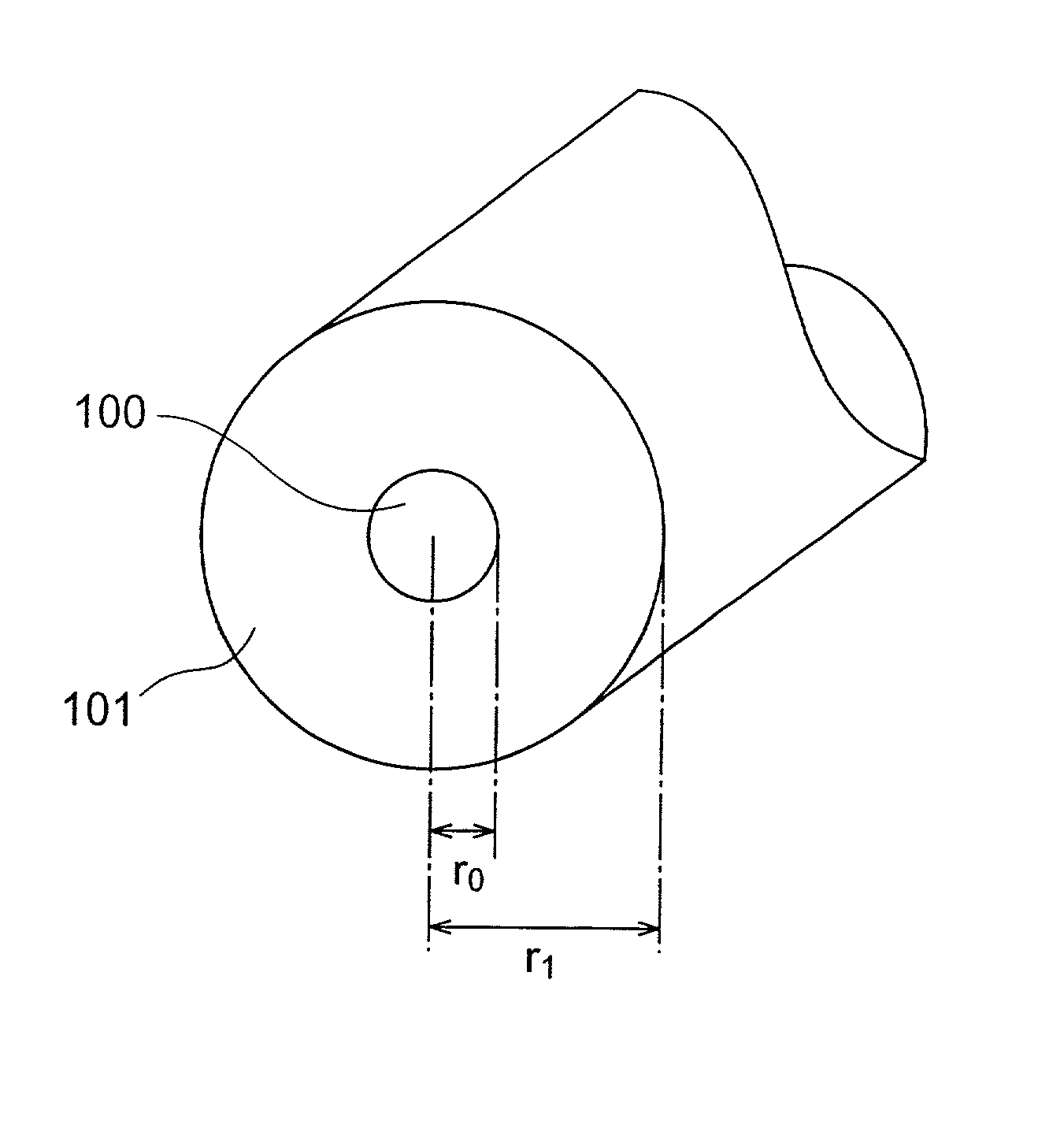
[0126] This optical fiber is an optical fiber of SiO.sub.2 glass (silica glass) type; and comprises a core region 600 including the center axis of the optical fiber, and a cladding region 700 provided at the outer periphery of the core region 600.

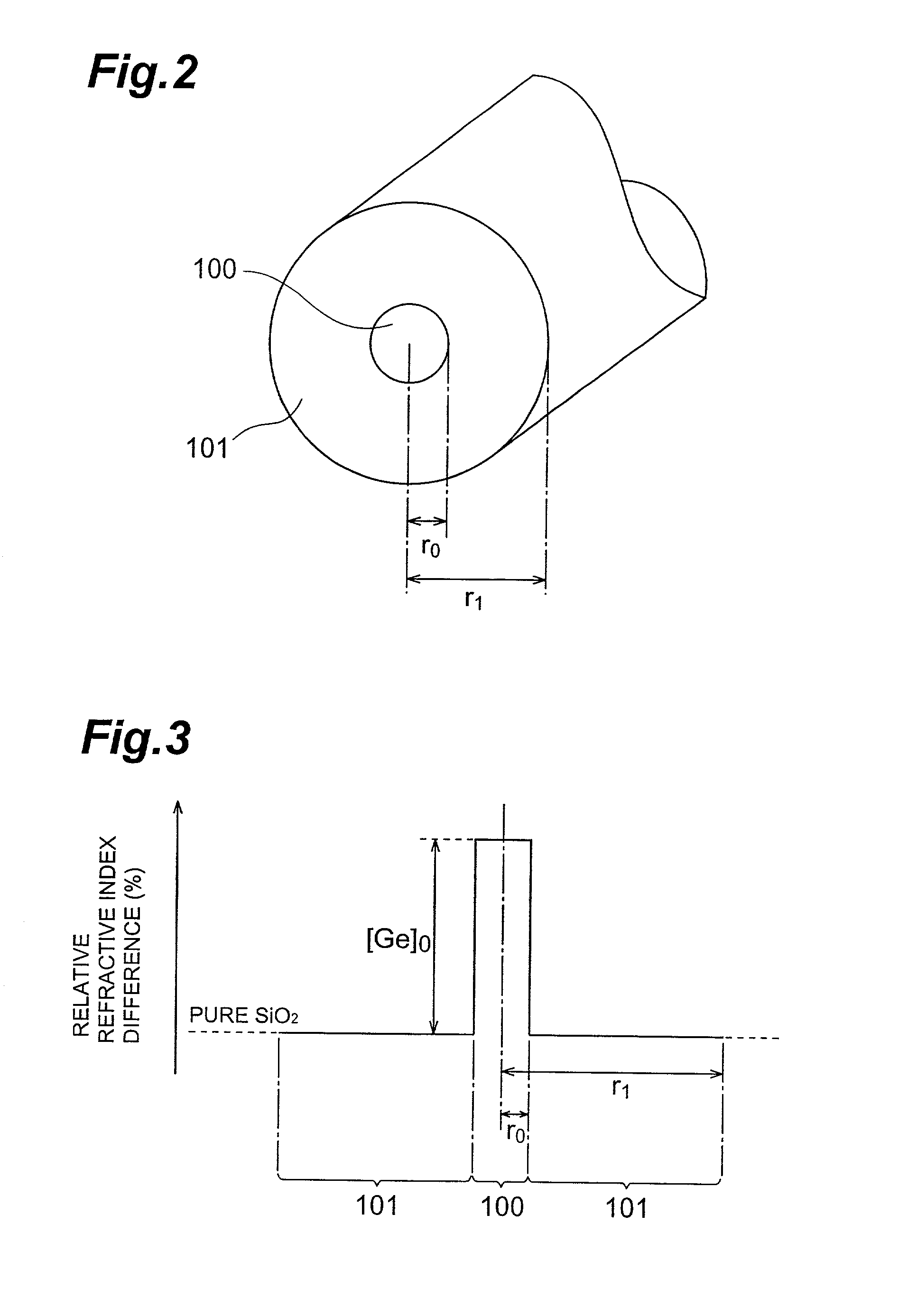
[0127] The core region 600 is formed such that the outer periphery thereof has a radius of r.sub.0. In the core region 600, pure SiO.sub.2 glass is doped with a predetermined amount of Cl (chlorine) as an additive for enhancing the refractive index. Consequently, the average relative refractive index difference within the core region 600 is .DELTA.n.sub.0 (where .DELTA.n.sub.0>0).

[0128] On the other hand, the cladding region 700 in this embodiment comprises two layers of cladding, i.e., an inner cladding layer 701 provided at the outer periphery of th...

second embodiment

[0138] FIG. 8 is a chart showing the refractive index profile of the second optical fiber in accordance with the present invention.

[0139] As in the first embodiment, this optical fiber is an optical fiber of SiO.sub.2 glass (silica glass) type; and comprises a core region 600 including the center axis of the optical fiber, and a cladding region 700 provided at the outer periphery of the core region 600.

[0140] The configurations of the core region 600 and cladding region 700 are substantially the same as those of the optical fiber shown in FIG. 7, but differ therefrom in the configuration of the outer cladding layer 702 of the cladding region 700. Namely, in this embodiment, the outer cladding layer 702 is not doped with F (fluorine), whereby it is made of pure SiO.sub.2. Therefore, the average relative refractive index differences of the cladding regions 701 and 702 have a relationship of 0=.DELTA.n.sub.2>.DELTA.n.sub.1.

[0141] The average relative refractive index difference .DELTA....

third embodiment

[0145] FIG. 9 is a chart showing the refractive index profile of the second optical fiber in accordance with the present invention.

[0146] As in the first and second embodiments, this optical fiber is an optical fiber of SiO.sub.2 glass (silica glass) type; and comprises a core region 600 including the center axis of the optical fiber, and a cladding region 700 provided at the outer periphery of the core region 600. Here, the configuration of the core region 600 is substantially the same as that of the core regions 600 of the optical fibers shown in FIGS. 7 and 8.

[0147] On the other hand, the cladding region 700 in this embodiment has a single cladding layer 701. The cladding layer 701 is formed such that the outer periphery thereof has a radius of r.sub.1. In the cladding layer 701, pure SiO.sub.2 glass is doped with a predetermined amount of F (fluorine) as an additive for lowering the refractive index. As a consequence, the average relative refractive index difference in the cladd...


PUM

PropertyMeasurementUnit
Fractionaaaaaaaaaa
Pressureaaaaaaaaaa
Pressureaaaaaaaaaa

Abstract

An optical fiber preform 2 having a viscosity ratio Reta=eta0/etat of 2.5 or less between the core average viscosity eta0 and the total average viscosity etat is prepared, and is drawn by a drawing furnace 11 so as to yield an optical fiber 3, which is then heated to a temperature within a predetermined range so as to be annealed by a heating furnace 21 disposed downstream the drawing furnace 11. Here, upon annealing in the heating furnace 21, the fictive temperature Tf within the optical fiber lowers, thereby reducing the Rayleigh scattering loss. At the same time, the viscosity ratio condition of Reta<=2.5 restrains the stress from being concentrated into the core, thereby lowering the occurrence of structural asymmetry loss and the like. Hence, anoptical fiber which can reduce the transmission loss caused by the Rayleigh scattering loss and the like as a whole, and a method of making the same can be obtained.

Description

[0001] 1. Field of the Invention[0002] The present invention relates to an optical fiber for transmitting light, and a method of making the same.[0003] 2. Related Background Art[0004] In the transmission of light using an optical fiber, the transmission loss (Rayleigh scattering loss) caused by Rayleigh scattering within the optical fiber becomes problematic. For this problem, an optical fiber which can reduce the Rayleigh scattering loss or a method of making the same has been proposed.[0005] For example, "Sakaguchi, the Transactions of the Institute of Electronics, Information and Communication Engineers, 2000 / 1, Vol. J83-C, No. 1, pp. 30-36", discloses that the Rayleigh scattering loss in an optical fiber can be reduced by annealing the optical fiber after drawing. Namely, the Rayleigh scattering intensity within glass is not constantly fixed by materials thereof, but depends on a fictive temperature Tf which is a virtual temperature indicative of the randomness in the state of a...

Claims


Application Information

Patent Timeline
IPC IPC(8): C03B37/027C03B37/029C03B37/15G02B6/02G02B6/036
CPCC03B37/02718C03B37/029C03B37/15C03B2201/12C03B2201/20G02B6/03627C03B2203/22C03B2205/56C03C13/04G02B6/02C03B2201/31C03B37/02727
Inventor NAGAYAMA, KATSUYAOHGA, YUICHISAITOH, TATSUHIKOISHIKAWA, SHINJITSUCHIYA, ICHIROUCHIYAMA, TAKENORI
Owner SUMITOMO ELECTRIC IND LTD
Why Eureka
Try Eureka