
Storage system for suppressing failures of storage media group

a storage media and failure technology, applied in the field of storage systems, can solve the problems of low deterioration of this storage medium, and achieve the effect of increasing capacity and decreasing price per unit capacity

Inactive Publication Date: 2008-02-07
HITACHI LTD
View PDF3 Cites 21 Cited by
  • Summary
  • Abstract
  • Description
  • Claims
  • Application Information

AI Technical Summary

Benefits of technology

[0013]There is a storage medium called a flash memory medium which uses a flash memory. A flash memory is a semiconductor device where data loss is not generated even if the supply of power is stopped, and data can be freely erased and written. Recently a flash memory medium using a semiconductor device called a “NAND type flash memory” in particular, is becoming popular, since its capacity is increasing and the price per unit capacity is decreasing.
[0014]Unlike an HDD, a flash memory medium does not have mechanical drive components, so the deterioration of this storage medium is low even after a long period of operation. Also the time to move the magnetic head by the rotation of the platter is not required, so the overhead time required for data retrieval can be decreased, and the response performance can be improved compared with an HDD.
[0019]In order to prevent failure of a storage media by such deterioration, a method of preventing local deterioration by evenly distributing the write amount on an entire flash memory, or a method of preparing an alternate block in case of failure generated in a specific area (hereafter called “flash memory deterioration suppression method”) is used.
[0025]With the foregoing in view, it is an object of the present invention to improve the availability of a storage system where a plurality of storage media, which deteriorate by writing, are installed.

Problems solved by technology

Unlike an HDD, a flash memory medium does not have mechanical drive components, so the deterioration of this storage medium is low even after a long period of operation.

Method used


Image

  • Storage system for suppressing failures of storage media group
  • Storage system for suppressing failures of storage media group
  • Storage system for suppressing failures of storage media group

Examples


embodiment 1

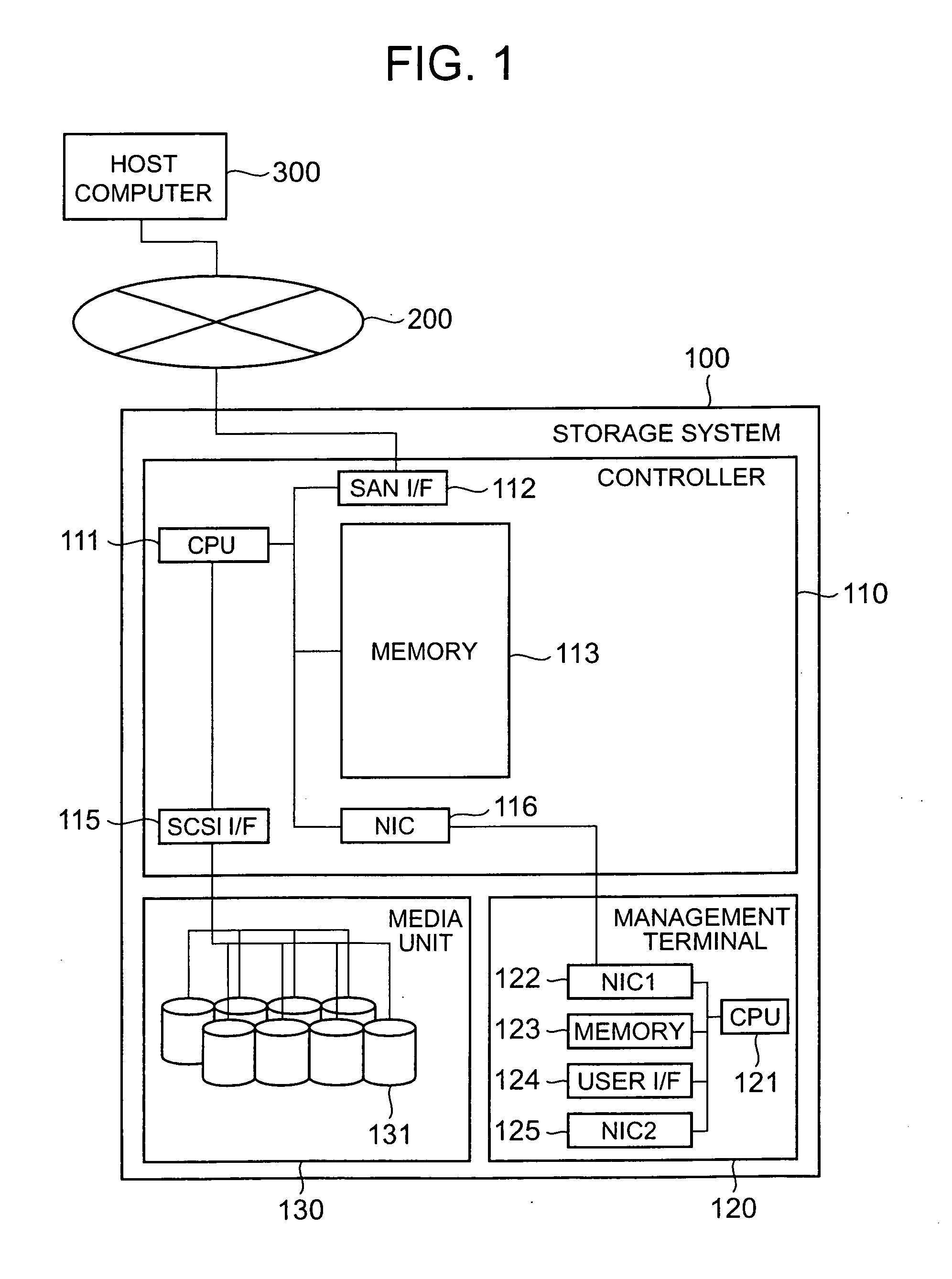
[0070]FIG. 1 is a diagram depicting the configuration example of the computer system according to the first embodiment of the present invention. In this embodiment, the storage system corresponds to the above mentioned storage system.

[0071]The configuration of the computer system will be described first.

[0072]A storage system 100 and a host computer 300 are connected to a storage network 200. A write request for writing data and a read request for reading data can be sent from the host computer 300 to the storage system 100.

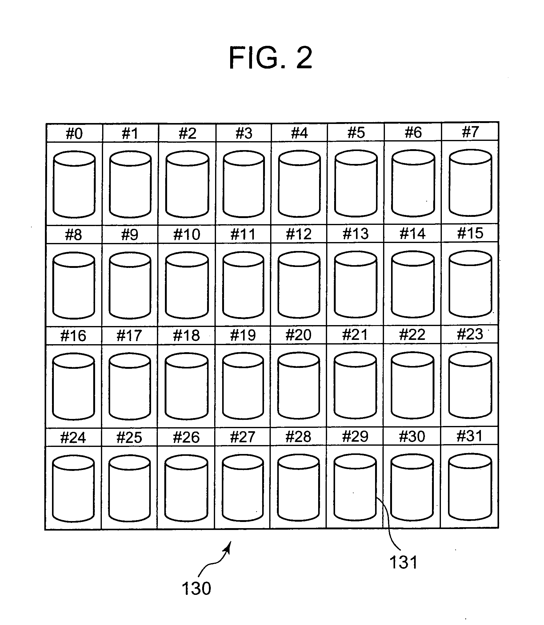
[0073]The storage system 100 is comprised of a media unit 130 for storing a plurality of flash memory media 131, a controller 110 for controlling each flash memory medium 131, and a management terminal 120 for managing this storage system 100. In the following description, a flash memory medium may simply be called a “medium”.

[0074]The controller 110 is comprised of a processor 111 for controlling this controller 110 entirely, a memory 113 for storing computer pr...

embodiment 2

[0189]The second embodiment of the present invention will now be described. In the following description, primarily the differences from the first embodiment will be described, and description of common aspects as the first embodiment will be omitted or simplified.

[0190]FIG. 18 is a diagram depicting the configuration of the computer system according to the second embodiment of the present invention.

[0191]First the configuration of the system will be described.

[0192]The host computer 300, storage network 200, storage system 100 and the components of the storage system 100, which are the controller 110, media unit 130, management terminal 120 and the network interface 125, which is a component of the management terminal 120, are the same as those described in the first embodiment (FIG. 1). The controller 110 additionally has a “volume migration function”. By this function, a logical volume in use and an unused logical volume are specified, and after data is copied from the logical vo...


PUM


Abstract

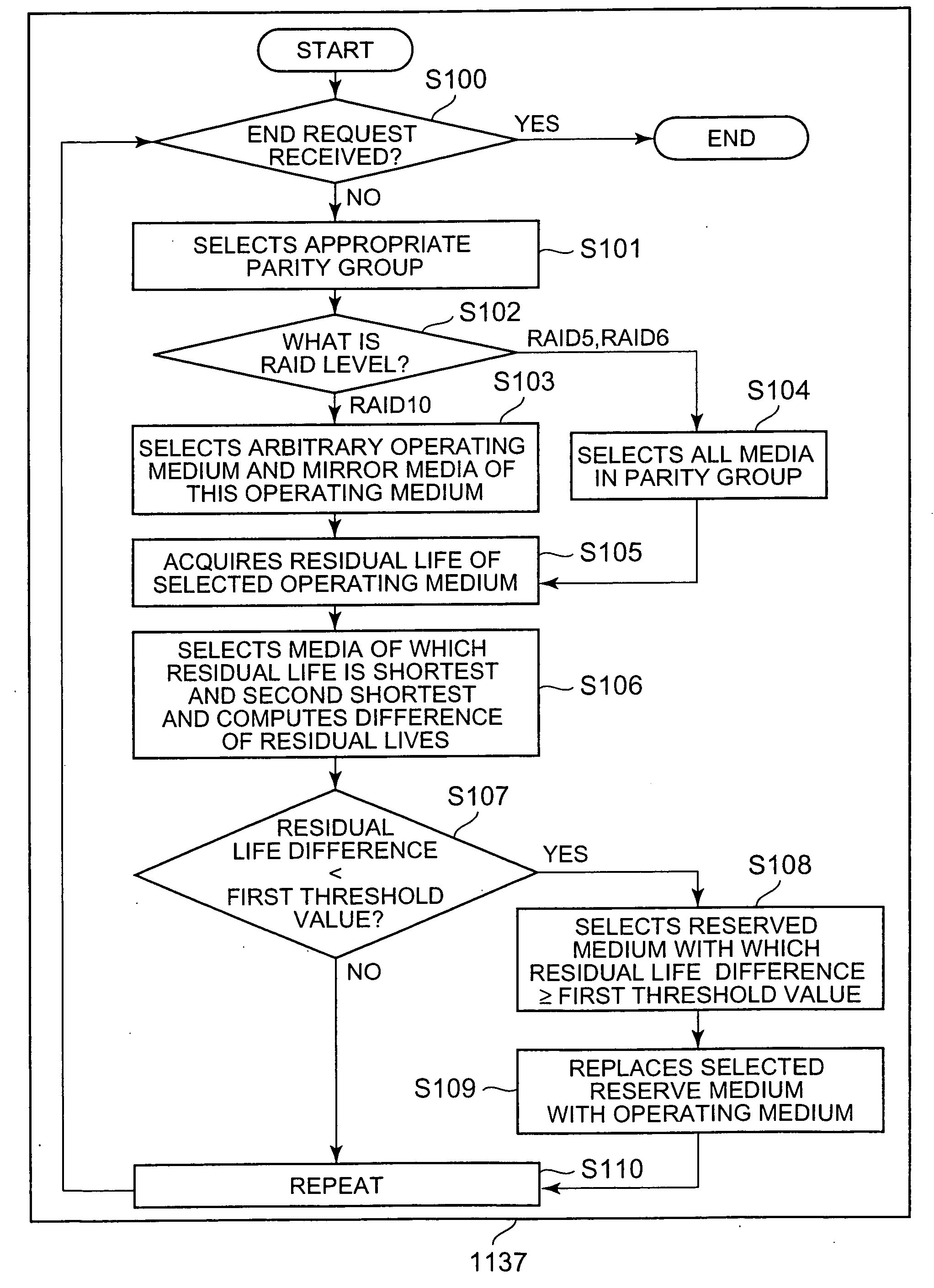
A consumption value of each storage medium and an upper limit related to writing are managed. Respective consumption value and the upper limit of each of two or more storage media out of a plurality of storage media constituting a storage media group are specified, and a remaining use period value is computed for each of the storage media using the upper limit and the consumption value. Based on each of the computed remaining use period values, data in at least one storage medium out of a plurality of storage media belonging to the selected storage area group is shifted to a storage medium which is different form the storage area group.

Description

CROSS-REFERENCE TO PRIOR APPLICATION[0001]This application relates to and claims priority from Japanese Patent Application No. 2006-212925, filed on Aug. 4, 2006, the entire disclosure of which is incorporated herein by reference.BACKGROUND[0002]1. Field of the Invention[0003]The present invention relates to a storage system having a plurality of storage media.[0004]2. Description of the Related Art[0005]In a conventional storage system, a plurality of storage media are integrated, and high performance, based on parallel access, and high availability by data redundancy, are implemented using a configuration called a RAID (Redundant Array of Inexpensive Disks).[0006]For this storage system, a storage medium called HDD (Hard Disk Drive) is normally used. An HDD is comprised of a disk called a platter where a magnetic substance for recording data is coated or deposited, a magnetic head for reading or changing the magnetic status of the platter, and a motor for rotating the platter so a...

Claims


Application Information

Patent Timeline
IPC IPC(8): G06F12/16
CPCG06F11/004G06F11/1076G06F11/2069G06F2211/1071G06F11/3485G06F2211/1057G06F2211/1059G06F11/2071
Inventor KAWAGUCHI, TOMOHIROKAWAMURA, SHUNJI
Owner HITACHI LTD
Learn More